Ultrasonic Thickness Gauging of Heavily Corroded Pipes
Application Overview:
Pipe integrity and corrosion monitoring is critical across many industries. These inspections are typically performed using ultrasonic thickness gauges, but severely corroded pipes can pose significant measurement challenges to the unprepared operator. This note is intended as a primer for how to get the most out of your Dakota NDT thickness gauge when inspecting heavily corroded pipework.
Measurement Challenges:


Good Pipe Echo Diagram
Bad Pipe Echo Diagram
Corroded pipes are difficult to measure for a couple of different reasons:
1) Rough surfaces disrupt transducer contact, scatter signals and in cases of heavy flaking, can make ultrasonic measurement extremely unreliable without surface preparation.
2) Complex Back Wall Echoes create low-amplitude, high-noise echo signals, making gating and signal analysis more difficult.
3) Material Loss introduces changes to geometry that can confuse the inspection, and can also occur in a very localised fashion, which requires better inspection coverage.
4) Coupling Issues can present from a combination of the rough surface and irregular geometry, slowing down the rate at which pipe can be inspected.
Techniques and Strategies
Transducer Selection
Transducer selection is key when inspecting difficult parts. In most cases, dual element transducers are significantly more suitable for corroded pipe inspections than single element contact or delay transducers. The separate send and receive crystals ensure that the near-surface resolution is good enough to identify thin areas and surface-cracks.
Frequency wise, in most cases we recommend choosing a transducer somewhere between 2.25MHz and 7.5MHz, depending on the pipe material to be inspected. For cast iron, or older, more-degraded steel, 2.25MHz ensures the transducer has the penetration to hit the back wall and return, whereas a 7.5MHz can give you better resolution for flaw identification at the cost of penetration power.
Minimum transducer range is also a very important consideration when using Numerical Thickness Gauges instead of A-Scan ones; below the transducer's minimum specified range you're likely to encounter 'double-reads', where thin material will measure twice as thick as it should because you're gating to the second echo instead of the first. This effect happens due to the near-field effect that affects all ultrasonic transducers.
Surface Preparation
Surface preparation is often crucial in scenarios where the corrosion is really advanced, as the flaked-off structure of the pipe can be almost impossible to measure through if an air-gap has developed beneath the surface.
For best results, use a wire-brush or bristle-blaster to remove loose rust flakes, scale or any dirt from excavating the pipe, as all of these will negatively contribute to reading quality. In severe cases, it might be necessary to carefully 'chip off' surface corrosion; extreme caution is necessary to avoid gouging or damaging the underlying pipe material. The goal is to remove loose corrosion, not to aggressively remove material from the pipe wall itself.
Couplant application is also an important consideration; rougher surfaces typically require significantly more couplant to ensure the area as wetted, as the surface area dramatically increases as surface corrosion develops. Sometimes it can be more suitable to use a high-viscosity couplant to stay on the surface longer.
A-Scan Parameters
- Material Velocity should be calibrated as close to a representative sample of the test metal as possible; the ideal scenario would be getting a cut-off section that can be accurately measured with a micrometre to provide 1 or 2 calibration points along the edge of the part. Alternatively, if you identify the specific alloy type, you can look up values online for reasonable acoustic velocity, or use the defaults provided in all Dakota non-destructive testing products.
- Gain Control is necessary to ensure that you've got enough amplification of the return echo to identify the proper back wall echo. If using a multiple-echo approach, Time Corrected Gain can be a powerful tool to ensure you can gate between the correct echoes.
- Gating should be managed intelligently to ensure front-surface noise is ignored. Similarly, if measuring in a multiple-echo mode, it's important that the Holdoff is set high enough to avoid measuring the same echo twice.
Temperature
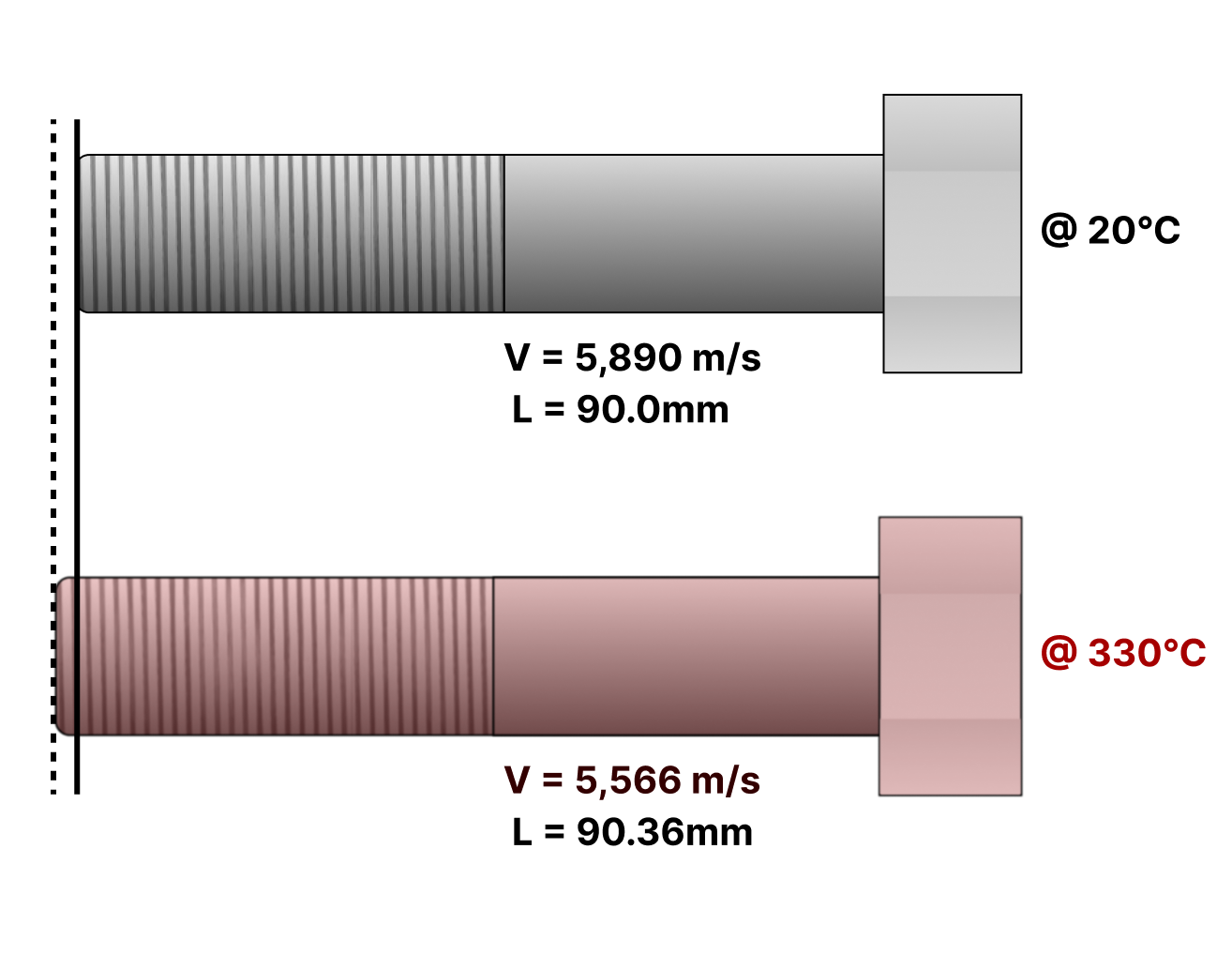
If required to inspect a high temperature pipe, certain precautions have to be taken to ensure the inspection is accurate, safe for the inspector and safe for the inspection equipment.
1) Ensure that the temperature's effect on the pipe's acoustic velocity is accounted for. The easiest way to do this is to calibrate on steel of the same type and temperature, but the Dakota CMX Corrosion Thickness range also come with the capability to automatically compensate for high-temperature effects on measurement using the PETP mode.
2) Ensure that the transducer never exceeds its maximum temperature during the inspection. For standard Dakota NDT ultrasonic transducers this temperature is 104ºC (220°F) for a constant connection, or 126°C (260°F) if taking 'intermittent' readings; this means taking the transducer off the surface rapidly after a measurement to ensure it cools down before the next one. When using high temperature transducers, the constant connection temperature is 260°C (500°F) and the intermittent temperature is 335°C (635°F).
3) If working with high temperature pipes, make sure the selected couplant is also in a suitable temperature range; exceeding the maximum could result in couplant boil-off, which smells bad and couples poorly to the surface. Dakota NDT provides a high-temperature paste-style couplant for use with high-temperature probes and applications.
Worked Example
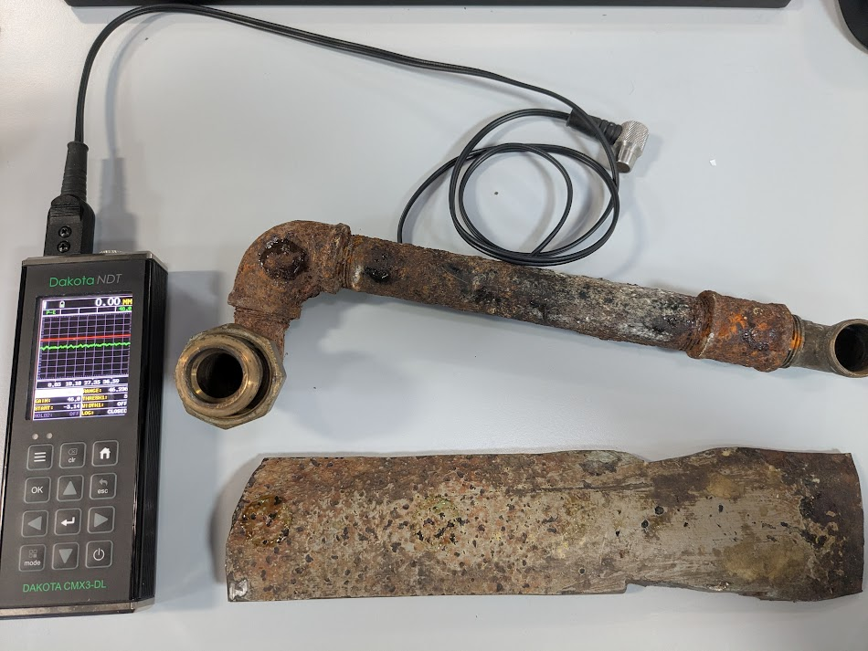
Samples
- Heavily corroded small-diameter pipe section with elbow joint & cuff
- Moderately corroded large-diameter pipe fragment
Inspection Goals
- Perform a corrosion map of both pipe sections
- Map large-diameter pipe section
- Map small-diameter pipe sections
Equipment
- Dakota CMX3-DL Ultrasonic Corrosion Gauge - Dakota NDT's most advanced A-Scan corrosion gauge, featuring a 60Hz refresh rate and significant measurement flexibility. Having multiple measurement modes, 110dB of gain adjustment, and a variable power pulser means it can deal with more or less anything.
- T-002-2700 - 5MHz .250" Highly-Damped Dual Element Ultrasonic Transducer - Due to the thin walled pipe having a potential minimum thickness of below 2mm, I needed to ensure the near-field zone wasn't too long to obscure anything that would appear in the front-half of the A-Scan trace.
Process
1) Calibrate ultrasonic thickness gauge
using micrometre along the edges of Large-Diameter Pipe Section, edge thickness points: 4.60mm (thin) & 6.25mm (thick) -> 5314.4 m/s
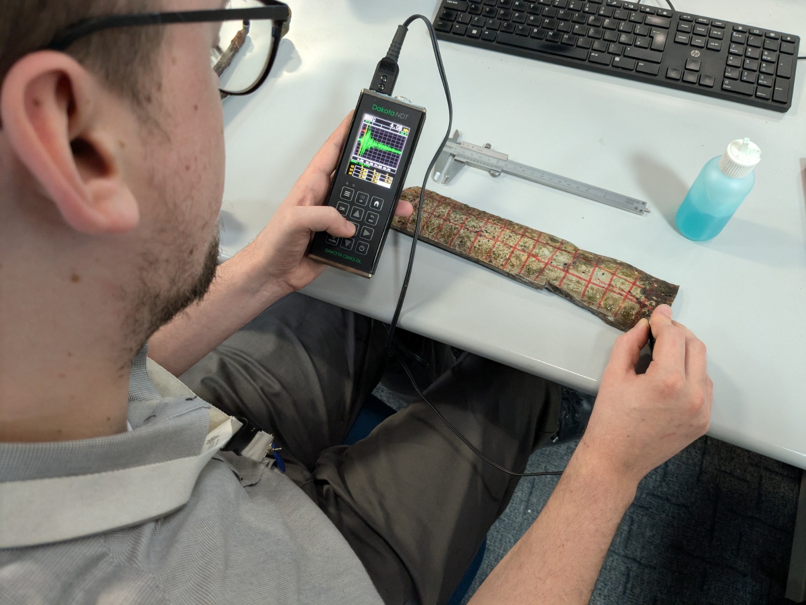
2) Draw out map of measurement points
15x3 (45 measurements) drawn with a red dry-wipe marker
3) Create grid data log on gauge
Matching the dimensions and sections of the maps drawn for the pipes.
4) Perform inspection
Making sure to keep the gauge's settings consistent.
5) Create Report
by downloading the data into DakMaster for further analysis.
Results
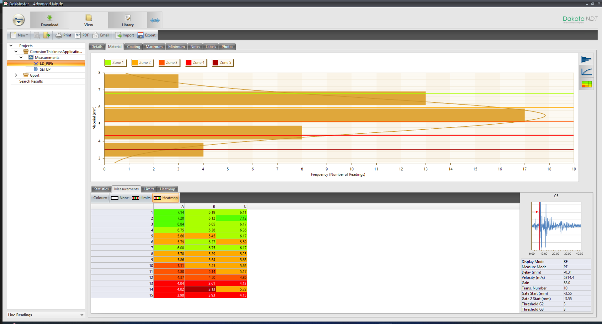
The data was transferred to DakMaster for analysis via a standard USB-C-to-USB-A cable. This allows us to download all of the readings including their A-Scan representation directly onto our PC. DakMaster then computes statistics related to the data-log and provides visualisations, such as these thickness histograms and a coloured heatmap.
In these images I've combined the heatmap from DakMaster with an image of the pipe to draw up a coloured map of the pipe. You can see from this image that the right hand side of the pipe section has experienced significantly more material loss than the left hand side.
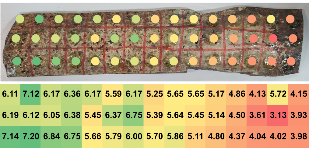

Rusty Pipe Corrosion Map
Thin Pipe Corrosion Map
The small-diameter pipe has a less consistent thickness reduction profile, with small hotspots around certain areas, such as the bend of the elbow joint. This pipe could stand to have a significantly more thorough inspection performed, perhaps doubling or tripling the amount of readings taken to better map the thin areas.
Conclusion
Measuring corrosion on pipes, particularly in severe cases, presents a significant inspection challenge. However, by understanding the complexities of ultrasonic measurement on corroded surfaces and applying the correct techniques, accurate and reliable thickness readings are readily achievable. Key to success is selecting the optimal Dakota NDT transducer, utilizing the advanced A-Scan features of gauges like the Dakota NDT Corrosion Thickness CMX-3 series, meticulous surface preparation, and following a robust measurement procedure. This application note provides a primer to equip operators to confidently assess even heavily corroded pipework, ensuring asset integrity and operational safety.
Contact Dakota NDT today to discuss your specific corrosion inspection needs and discover how our ultrasonic thickness gauges and expert support can help you "measure the unmeasurable." Our team is ready to assist you in selecting the right equipment and implementing effective corrosion monitoring programs.
Dakota equipment used in this application:
For more details on how the Dakota CMX Corrosion Thickness Gauge can give an advantage to your inspection process.