

Dakota CMX Corrosion Thickness Gauges
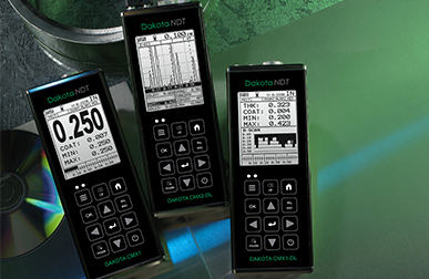
Top of the range and easy to use, the Dakota CMX Corrosion Thickness Gauges provide inspectors with all the features necessary to measure the material and coating thickness at the same time.
- 要約
-
要約
-
Intelligent
User definable limits for pass/fail indication
Set limits for pass/fail indication on individual reading or for each batch with audible & visual warnings.
Powerful
Store each measurement for further analysis
Up to 4GB of readings can be saved into the gauge memory as each measurement is taken, which can be downloaded later into an inspection application or into DakMaster™ Software for further analysis and reporting.
Versatile
Able to measure coating and material thickness
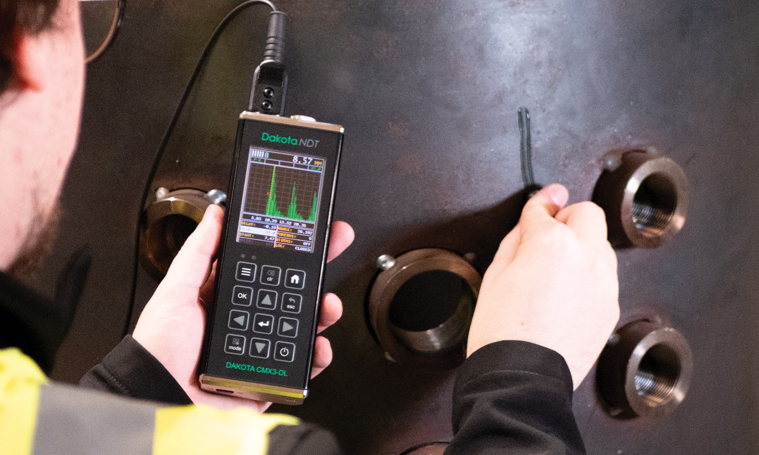
The Dakota CMX Ultrasonic Corrosion Thickness Gauges have the ability to measure coatings and material thickness simultaneously while maintaining the ability to locate pits, flaws and defects in the material.
Customisable
Choose & customise the reading display
The Dakota CMX Corrosion Thickness Gauge range has a choice of display modes allowing the user to select the most appropriate for their needs; Readings, B-Scan, B-Scan combined with readings, Scan bar & the A-Scan on the Dakota CMX2-DL Corrosion Thickness Gauge and Dakota CMX3-DL Corrosion Thickness Gauge.
The Dakota CMX ultrasonic corrosion thickness gauge is available in four models - from an entry level Dakota CMX1-DL Ultrasonic Corrosion Thickness Gauge to the top of the range Dakota CMX3-DL Ultrasonic Corrosion Thickness Gauge.
- Range of display & measurement options: Pulse-Echo, Echo-Echo, Pulse-Echo Temp, Comp Mode (PETP), Coating Only Mode (CT), Pulse-Echo Coating Mode (PECT)
- Manual or automatic gain control (AGC) with adjustable 110dB range
- Gate control
- Threshold adjustment
- 64 User defined setups
- Multiple language display
- Multiple calibration and material selection options
- High speed scan mode: 250 readings per second (Dakota CMX1-DL Ultrasonic Corrosion Thickness Gauge), 50 readings per second (Dakota CMX2-DL Ultrasonic Corrosion Thickness Gauge and Dakota CMX3-DL Ultrasonic Corrosion Thickness Gauge)
- A-Scan portrait & landscape views (Dakota CMX3-DL Ultrasonic Corrosion Thickness Gauge only)
- Differential and minimal thickness alarm modes
- Data output and storage: 4GB internal memory
- Download to DakMaster™ data management software
-
- 特長
-
特長
Dakota CMX Corrosion Thickness Gauges
Support & Resources
Transducer Options
A wide range of Corrosion Thickness Transducers available.
DakMaster™
From inspection to professional reports at the click of a button.
Application Notes
Explore how to get the most out of your Dakota CMX Gauge.
Dakota CMX Features Explained
Repeatability / Stability Indicator
Consisting of 6 vertical bars, when all the bars are fully illuminated and the last digit on the digital thickness value is stable, the gauge is reliably measuring the material thickness.
High Speed Scan with Minimum Thickness Display
By significantly increasing the measurement refresh rate this mode allows the user to make scanned passes over the test material. The smallest thickness value is held in memory and displayed when scanning is complete. This feature can also be used in conjunction with the minimum & maximum limit alarm feature (model dependant).
Differential Mode
Once a user defined nominal thickness value has been set, the gauge will display the +/- thickness difference from the nominal value entered.
Limit Alarm Mode
The user can define minimum and maximum thickness limits. If the measurement falls outside the upper or lower limit a red LED will light and the beeper sounds. A green LED will light to indicate an acceptable thickness.
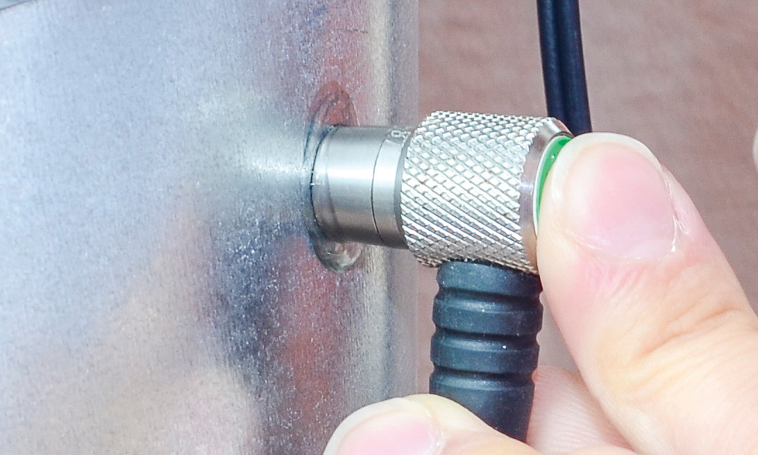
V-Path Correction
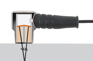
Dual element transducers consist of a probe with two crystals (one to transmit and one to receive the sound pulse). The crystals are separated by an acoustic barrier - generating a 'V-shaped' sound path as the sound travels from one element to the other. This path is slightly longer than the direct path therefore V-path correction is used to calculate the correct thickness
Measurement Modes Explained
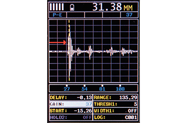
Pulse - Echo Mode (PE):
The normal display mode, measures the total thickness from the base of the transducer probe to the material density boundary (typically the back wall). Ideal for pit and flaw detection.
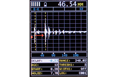
Echo - Echo Mode (EE):
Also known as the ThruPaint™ Mode, EE ignores the coating thickness, displaying the material thickness from the top surface of the material to the material density boundary.
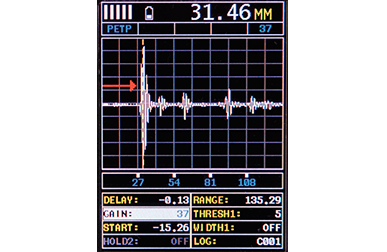
Pulse - Echo Temp Comp Mode (PETP):
Similar to the PE mode, PETP takes into account and compensates for the variations in measurement caused by temperature variations.
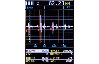
Echo - Echo Verify Mode (EEV):
The echo-echo verify mode measures by comparing the values between 3 reflections and is commonly used to eliminate errors from surface coatings and to make measurements in multiple layered materials.
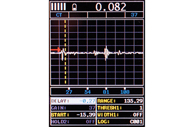
Coating Only Mode (CT):
Displays the thickness of the coating applied to the material.
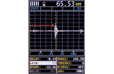
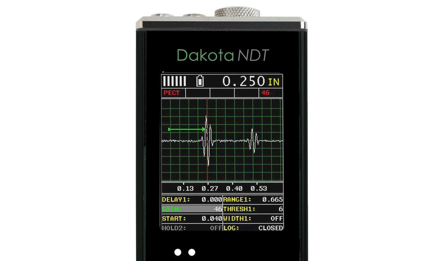
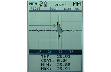
Pulse - Echo Coating Mode (PECT):
Displays both the material thickness (PE) and the coating thickness (CT) at the same time.
Basic Flaw Mode (FLAW MODE):
Basic prove-up flaw detection using single element angle beam transducers is available on the CMX2-DL and CMX3-DL corrosion thickness gauges.
Display Modes Explained
Material Thickness Digits Display:
The standard display on all models, this displays the numerical thickness value in either millimetres (MM)or inches (IN).
Scan Bar Display:
A linear graphic display which allows users to graphically monitor changes in thickness readings. As the scale range can be adjusted by the user, this display is ideal for observing tiny variations in material thicknesses.
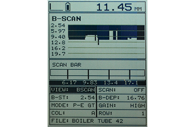
B-Scan Display:
A time based cross sectional 2D block view of the thickness provides a graphical view of the material thickness - ideal for relative depth analysis.
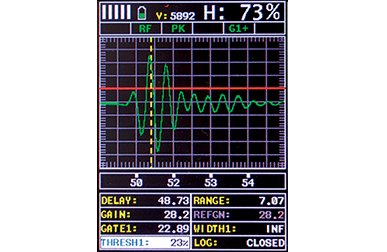
A-Scan Display; Full Wave (RF):*
The A-Scan display shows the sine wave created by the reflected sound, or oscillation, from the material being measured. In RF mode the full wave form is displayed.
A-Scan Display; Rectified (+ or -):*
Users can select to view either the positive or the negative cycle of the full waveform (RF). This rectified (RECT) display shows the amplitude of the echo versus the transit time.
* Available on CMX2-DL and CMX3-DL thickness gauge Models only
Firmware Upgrades
Regularly checking and updating your firmware is crucial for maintaining performance, and ensuring compatibility with new features.
Make sure your Dakota Corrosion Thickness Gauge is running the latest firmware, select your gauge below.
Dakota Ultrasonics CMX
Dakota NDT CMX
-
- 製品の特長
-
製品の特長Dakota CMX Corrosion Thickness Gauges
Model CMX1-DL CMX2-DL CMX3-DL 表示モード 厚さ - 数値 Bスキャン(断面図) Bスキャンと数値の組み合わせ 膜厚 スキャンバー Aスキャン 正半波、負半波、全波(RF)正半波、負半波、全波(RF) ンデータ画面の表示を横長・縦長に変更可能CMX Measurement Range PE: 0.63 - 1219.2mm
(0.025 - 48”)
PETP: 0.63 - 1219.2mm
(0.025 - 48”)
EE: 2.54 - 152.4mm
(0.100 - 6.0“)
EEV: 1.27 - 25.4mm
(0.050 - 1.0”)
CT: 0.01 - 2.54mm
(0.0005 - 0.100”)
PECT: 0.63 - 1219.2mm
(0.025 - 48”)
PECT: 0.01 - 2.54mm
(0.001 - 0.100")PE: 0.63 - 1219.2mm
(0.025 - 48”)
PETP: 0.63 - 1219.2mm
(0.025 - 48”)
EE: 2.54 - 152.4mm
(0.100 - 6.0“)
EEV: 1.27 - 25.4mm
(0.050 - 1.0”)
CT: 0.01 - 2.54mm
(0.0005 - 0.100”)
PECT: 0.63 - 1219.2mm
(0.025 - 48”)
PECT: 0.01 - 2.54mm
(0.001 - 0.100")PE: 0.63 - 1219.2mm
(0.025 - 48”)
PETP: 0.63 - 1219.2mm
(0.025 - 48”)
EE: 2.54 - 152.4mm
(0.100 - 6.0“)
EEV: 1.27 - 25.4mm
(0.050 - 1.0”)
CT: 0.01 - 2.54mm
(0.0005 - 0.100”)
PECT: 0.63 - 1219.2mm
(0.025 - 48”)
PECT: 0.01 - 2.54mm
(0.001 - 0.100")Measurement Rate 手動 1秒間に8回読み取り1秒間に8回読み取り1秒間に8回読み取りスキャンモード 1秒間に250回読み取り1秒間に50回読み取り1秒間に50回読み取りスキャンバー 33 Hz33 Hz33 Hz分解能 0.01mm (0.001インチ)0,001mm(0.0001インチ)選択可能0,001mm(0.0001インチ)選択可能速度の校正範囲 309.88~18,542m/秒 (0.0122~0.73インチ/マイクロ秒)309.88~18,542m/秒 (0.0122~0.73インチ/マイクロ秒)309.88~18,542m/秒 (0.0122~0.73インチ/マイクロ秒)その他の機能 高速スキャンモード 差分モード 制限値のアラームモード Bスキャン表示速度 1画面あたり10 ~ 200秒1画面あたり10 ~ 200秒1画面あたり10 ~ 200秒探傷モード 一振動子の斜角探触子を使用した簡易検査一振動子の斜角探触子を使用した簡易検査測定条件の設定 ユーザーが64件までの測定条件を設定し て、PCに転送可能ゲート 3個、開始点、停止点、幅、しきい値を調節 可能3個、開始点、停止点、幅、しきい値を調節 可能減衰 調節可能な減衰(50 ~ 1500Ω)調節可能な減衰(50 ~ 1500Ω)パルス発振器 横波パルス発振器2個
パルス繰り返し周波数(最大250Hz)横波パルス発振器2個
パルス繰り返し周波数(最大250Hz)横波パルス発振器2個
パルス繰り返し周波数(最大250Hz)ゲイン 範囲110dBの自動調節(AGC)、またはレベル (最低、低、中、高、最高) を選択範囲110dBの自動調節(AGC)、またはレベル (最低、低、中、高、最高) を選択, 直線型時間依存ゲイン(TDG)(スロープ を調節可能)範囲110dBの自動調節(AGC)、またはレベル (最低、低、中、高、最高) を選択, 直線型時間依存ゲイン(TDG)(スロープ を調節可能)タイミング制御 高精度TCXO(温度補償水晶発振器)1回発振 100MHzの低消費電力8ビットデジタイザー高精度TCXO(温度補償水晶発振器)1回発振 100MHzの低消費電力8ビットデジタイザー高精度TCXO(温度補償水晶発振器)1回発振 100MHzの低消費電力8ビットデジタイザーメモリとデータの記録 • 4GBの内蔵メモリ
• 連続データと表形式データ
• 英数字のバッチID
• OBSTRUCTは、測定不可能な部位を示す
• ビットマップ画像の撮影と画像ビューア• 4GBの内蔵メモリ
• 連続データと表形式データ
• 英数字のバッチID
• OBSTRUCTは、測定不可能な部位を示す
• ビットマップ画像の撮影と画像ビューア• 4GBの内蔵メモリ
• 連続データと表形式データ
• 英数字のバッチID
• OBSTRUCTは、測定不可能な部位を示す
• ビットマップ画像の撮影と画像ビューア校正方法 1点式 2点式 種類の材質から選択 音速入力 探触子の型 二振動子Dual Element, Single Element (1 - 20Mhz), ContactDual Element, Single Element (1 - 20Mhz), Contact周波数の範囲 1 - 10MHz1 - 10MHz1 - 20MHz探触子の認識 自動および手動 - リストから選択自動および手動 - リストから選択自動および手動 - リストから選択Vパス補正(二振動子の路程誤差補正) 自動自動自動プローブのゼロ値設定 自動および手動(内蔵ディスク使用)自動および手動(内蔵ディスク使用)自動および手動(内蔵ディスク使用)画面 1/8 VGA(グレースケール)
表示域62 x 45.7mm(2.4 x 1.8インチ)1/8 VGA(グレースケール)
表示域62 x 45.7mm(2.4 x 1.8インチ)¼ VGA、AMOLED採用カラーディスプレイ
表示域57.6 x 43.2mm(2.27 x 1.78インチ)
横長モード画面のリフレッシュレート 25Hz25Hz60Hz単位(選択可能) mmまたはインチmmまたはインチmmまたはインチLEDのバックライト オン/オフ/自動オン/オフ/自動明るさ調整可能繰り返し性と安定性のインジケーター 節電モード 自動自動自動表示モード 厚さ - 数値 Z-171-0005 Z-172-0005 Z-187-0005 Bスキャン(断面図) Z-171-0005 Z-172-0005 Z-187-0005 Bスキャンと数値の組み合わせ Z-171-0005 Z-172-0005 Z-187-0005 膜厚 Z-171-0005 Z-172-0005 Z-187-0005 スキャンバー Z-171-0005 Z-172-0005 Z-187-0005 Aスキャン Z-171-0005 Z-172-0005 正半波、負半波、全波(RF)Z-187-0005 正半波、負半波、全波(RF) ンデータ画面の表示を横長・縦長に変更可能CMX Measurement Range Z-171-0005 PE: 0.63 - 1219.2mm
(0.025 - 48”)
PETP: 0.63 - 1219.2mm
(0.025 - 48”)
EE: 2.54 - 152.4mm
(0.100 - 6.0“)
EEV: 1.27 - 25.4mm
(0.050 - 1.0”)
CT: 0.01 - 2.54mm
(0.0005 - 0.100”)
PECT: 0.63 - 1219.2mm
(0.025 - 48”)
PECT: 0.01 - 2.54mm
(0.001 - 0.100")Z-172-0005 PE: 0.63 - 1219.2mm
(0.025 - 48”)
PETP: 0.63 - 1219.2mm
(0.025 - 48”)
EE: 2.54 - 152.4mm
(0.100 - 6.0“)
EEV: 1.27 - 25.4mm
(0.050 - 1.0”)
CT: 0.01 - 2.54mm
(0.0005 - 0.100”)
PECT: 0.63 - 1219.2mm
(0.025 - 48”)
PECT: 0.01 - 2.54mm
(0.001 - 0.100")Z-187-0005 PE: 0.63 - 1219.2mm
(0.025 - 48”)
PETP: 0.63 - 1219.2mm
(0.025 - 48”)
EE: 2.54 - 152.4mm
(0.100 - 6.0“)
EEV: 1.27 - 25.4mm
(0.050 - 1.0”)
CT: 0.01 - 2.54mm
(0.0005 - 0.100”)
PECT: 0.63 - 1219.2mm
(0.025 - 48”)
PECT: 0.01 - 2.54mm
(0.001 - 0.100")Measurement Rate 手動 Z-171-0005 1秒間に8回読み取りZ-172-0005 1秒間に8回読み取りZ-187-0005 1秒間に8回読み取りスキャンモード Z-171-0005 1秒間に250回読み取りZ-172-0005 1秒間に50回読み取りZ-187-0005 1秒間に50回読み取りスキャンバー Z-171-0005 33 HzZ-172-0005 33 HzZ-187-0005 33 Hz分解能 Z-171-0005 0.01mm (0.001インチ)Z-172-0005 0,001mm(0.0001インチ)選択可能Z-187-0005 0,001mm(0.0001インチ)選択可能速度の校正範囲 Z-171-0005 309.88~18,542m/秒 (0.0122~0.73インチ/マイクロ秒)Z-172-0005 309.88~18,542m/秒 (0.0122~0.73インチ/マイクロ秒)Z-187-0005 309.88~18,542m/秒 (0.0122~0.73インチ/マイクロ秒)その他の機能 高速スキャンモード Z-171-0005 Z-172-0005 Z-187-0005 差分モード Z-171-0005 Z-172-0005 Z-187-0005 制限値のアラームモード Z-171-0005 Z-172-0005 Z-187-0005 Bスキャン表示速度 Z-171-0005 1画面あたり10 ~ 200秒Z-172-0005 1画面あたり10 ~ 200秒Z-187-0005 1画面あたり10 ~ 200秒探傷モード Z-171-0005 Z-172-0005 一振動子の斜角探触子を使用した簡易検査Z-187-0005 一振動子の斜角探触子を使用した簡易検査測定条件の設定 Z-171-0005 Z-172-0005 Z-187-0005 ユーザーが64件までの測定条件を設定し て、PCに転送可能ゲート Z-171-0005 Z-172-0005 3個、開始点、停止点、幅、しきい値を調節 可能Z-187-0005 3個、開始点、停止点、幅、しきい値を調節 可能減衰 Z-171-0005 Z-172-0005 調節可能な減衰(50 ~ 1500Ω)Z-187-0005 調節可能な減衰(50 ~ 1500Ω)パルス発振器 Z-171-0005 横波パルス発振器2個
パルス繰り返し周波数(最大250Hz)Z-172-0005 横波パルス発振器2個
パルス繰り返し周波数(最大250Hz)Z-187-0005 横波パルス発振器2個
パルス繰り返し周波数(最大250Hz)ゲイン Z-171-0005 範囲110dBの自動調節(AGC)、またはレベル (最低、低、中、高、最高) を選択Z-172-0005 範囲110dBの自動調節(AGC)、またはレベル (最低、低、中、高、最高) を選択, 直線型時間依存ゲイン(TDG)(スロープ を調節可能)Z-187-0005 範囲110dBの自動調節(AGC)、またはレベル (最低、低、中、高、最高) を選択, 直線型時間依存ゲイン(TDG)(スロープ を調節可能)タイミング制御 Z-171-0005 高精度TCXO(温度補償水晶発振器)1回発振 100MHzの低消費電力8ビットデジタイザーZ-172-0005 高精度TCXO(温度補償水晶発振器)1回発振 100MHzの低消費電力8ビットデジタイザーZ-187-0005 高精度TCXO(温度補償水晶発振器)1回発振 100MHzの低消費電力8ビットデジタイザーメモリとデータの記録 Z-171-0005 • 4GBの内蔵メモリ
• 連続データと表形式データ
• 英数字のバッチID
• OBSTRUCTは、測定不可能な部位を示す
• ビットマップ画像の撮影と画像ビューアZ-172-0005 • 4GBの内蔵メモリ
• 連続データと表形式データ
• 英数字のバッチID
• OBSTRUCTは、測定不可能な部位を示す
• ビットマップ画像の撮影と画像ビューアZ-187-0005 • 4GBの内蔵メモリ
• 連続データと表形式データ
• 英数字のバッチID
• OBSTRUCTは、測定不可能な部位を示す
• ビットマップ画像の撮影と画像ビューア校正方法 1点式 Z-171-0005 Z-172-0005 Z-187-0005 2点式 Z-171-0005 Z-172-0005 Z-187-0005 種類の材質から選択 Z-171-0005 Z-172-0005 Z-187-0005 音速入力 Z-171-0005 Z-172-0005 Z-187-0005 探触子の型 Z-171-0005 二振動子Z-172-0005 Dual Element, Single Element (1 - 20Mhz), ContactZ-187-0005 Dual Element, Single Element (1 - 20Mhz), Contact周波数の範囲 Z-171-0005 1 - 10MHzZ-172-0005 1 - 10MHzZ-187-0005 1 - 20MHz探触子の認識 Z-171-0005 自動および手動 - リストから選択Z-172-0005 自動および手動 - リストから選択Z-187-0005 自動および手動 - リストから選択Vパス補正(二振動子の路程誤差補正) Z-171-0005 自動Z-172-0005 自動Z-187-0005 自動プローブのゼロ値設定 Z-171-0005 自動および手動(内蔵ディスク使用)Z-172-0005 自動および手動(内蔵ディスク使用)Z-187-0005 自動および手動(内蔵ディスク使用)画面 Z-171-0005 1/8 VGA(グレースケール)
表示域62 x 45.7mm(2.4 x 1.8インチ)Z-172-0005 1/8 VGA(グレースケール)
表示域62 x 45.7mm(2.4 x 1.8インチ)Z-187-0005 ¼ VGA、AMOLED採用カラーディスプレイ
表示域57.6 x 43.2mm(2.27 x 1.78インチ)
横長モード画面のリフレッシュレート Z-171-0005 25HzZ-172-0005 25HzZ-187-0005 60Hz単位(選択可能) Z-171-0005 mmまたはインチZ-172-0005 mmまたはインチZ-187-0005 mmまたはインチLEDのバックライト Z-171-0005 オン/オフ/自動Z-172-0005 オン/オフ/自動Z-187-0005 明るさ調整可能繰り返し性と安定性のインジケーター Z-171-0005 Z-172-0005 Z-187-0005 節電モード Z-171-0005 自動Z-172-0005 自動Z-187-0005 自動1 Measuring range & accuracy depends on material, surface conditions and the transducer selected
-
- 仕様
-
Technical SpecificationDakota CMX Corrosion Thickness Gauges
Part Number Description Certificate Z-171-0005 Dakota CMX1-DL Thickness Gauge (CMX-DL) 
Z-172-0005 Dakota CMX2-DL Thickness Gauge (CMX-DL+) Z-187-0005 Dakota CMX3-DL Thickness Gauge (CMX-DL+ Colour) 探触子の型 二振動子型 測定精度 0.1mm (0.01インチ) メモリ容量 4GBの内蔵メモリ 使用温度 -10~60ºC (14~140ºF) データ出力 USB 電源 AA電池3本またはUSB接続 電池の寿命 アルカリ電池:グレースケール表示で35時間、カラー表示で12時間, ニッケルカドミウム電池:グレースケール表示で10時間、カラー表示で5時間, ニッケル水素電池:グレースケール表示で35時間、カラー表示で12時間 本体重量 383g (13.5 ンス) - 電池を含む 本体寸法 63.5 x 165 x 31.5mm (2.5 x 6.5 x 1.24インチ) 内用品 Unit, Selectable Transducer, Couplant, Manual, Plastic Carrying Case, Certificate of Calibration and AA Batteries. PC Software and Data Transfer Cable included with data logging gauges. 1Measuring range & accuracy depends on material, surface conditions and the transducer selected
2Approximate battery life, when in continuous measurement mode.
● Certificate of Calibration supplied as standard.
-
- 適合規格
-
適合規格Dakota CMX Corrosion Thickness Gauges
Factory calibration traceable to NIST & MIL-STD-45662
-
- ダウンロード
-
ダウンロード
-

Elcometer NDT モデル CG100B, CG100BDL & CG100ABDL - 取扱説明書
-
Elcometer NDT モデル CG100ABDL+ - 取扱説明書
-

超音波厚さ計 CG100 - データシート
-
超音波厚さ計 CG100B - 適合宣言書
-
超音波厚さ計 CG100BDL - 適合宣言書
-
超音波厚さ計 CG100ABDL - 適合宣言書
-
超音波厚さ計 CG100ABDL+ - 適合宣言書
- コード番号
-
コード番号Dakota CMX Corrosion Thickness Gauges
-
 Dakota CMX1-DL Corrosion Thickness Gauge
- コード番号 : Z-171-0005
-
 Dakota CMX2-DL Corrosion Thickness Gauge
- コード番号 : Z-172-0005
-
 Dakota CMX3-DL Corrosion Thickness Gauge
- コード番号 : Z-187-0005
Dakota CMX Corrosion Thickness Gauges
Top of the range and easy to use, the Dakota CMX Corrosion Thickness Gauges provide inspectors with all the features necessary to measure the material and coating thickness at the same time.
Intelligent
User definable limits for pass/fail indication
Set limits for pass/fail indication on individual reading or for each batch with audible & visual warnings.
Powerful
Store each measurement for further analysis
Up to 4GB of readings can be saved into the gauge memory as each measurement is taken, which can be downloaded later into an inspection application or into DakMaster™ Software for further analysis and reporting.
Versatile
Able to measure coating and material thickness
The Dakota CMX Ultrasonic Corrosion Thickness Gauges have the ability to measure coatings and material thickness simultaneously while maintaining the ability to locate pits, flaws and defects in the material.
Customisable
Choose & customise the reading display
The Dakota CMX Corrosion Thickness Gauge range has a choice of display modes allowing the user to select the most appropriate for their needs; Readings, B-Scan, B-Scan combined with readings, Scan bar & the A-Scan on the Dakota CMX2-DL Corrosion Thickness Gauge and Dakota CMX3-DL Corrosion Thickness Gauge.
要約
Dakota CMX Corrosion Thickness Gauges
The Dakota CMX ultrasonic corrosion thickness gauge is available in four models - from an entry level Dakota CMX1-DL Ultrasonic Corrosion Thickness Gauge to the top of the range Dakota CMX3-DL Ultrasonic Corrosion Thickness Gauge.
- Range of display & measurement options: Pulse-Echo, Echo-Echo, Pulse-Echo Temp, Comp Mode (PETP), Coating Only Mode (CT), Pulse-Echo Coating Mode (PECT)
- Manual or automatic gain control (AGC) with adjustable 110dB range
- Gate control
- Threshold adjustment
- 64 User defined setups
- Multiple language display
- Multiple calibration and material selection options
- High speed scan mode: 250 readings per second (Dakota CMX1-DL Ultrasonic Corrosion Thickness Gauge), 50 readings per second (Dakota CMX2-DL Ultrasonic Corrosion Thickness Gauge and Dakota CMX3-DL Ultrasonic Corrosion Thickness Gauge)
- A-Scan portrait & landscape views (Dakota CMX3-DL Ultrasonic Corrosion Thickness Gauge only)
- Differential and minimal thickness alarm modes
- Data output and storage: 4GB internal memory
- Download to DakMaster™ data management software
ダウンロード-
Elcometer NDT モデル CG100B, CG100BDL & CG100ABDL - 取扱説明書
-
Elcometer NDT モデル CG100ABDL+ - 取扱説明書
-
超音波厚さ計 CG100 - データシート
-
超音波厚さ計 CG100B - 適合宣言書
-
超音波厚さ計 CG100BDL - 適合宣言書
-
超音波厚さ計 CG100ABDL - 適合宣言書
-
超音波厚さ計 CG100ABDL+ - 適合宣言書
特長
Dakota CMX Corrosion Thickness Gauges
Support & Resources
Transducer Options
A wide range of Corrosion Thickness Transducers available.
DakMaster™
From inspection to professional reports at the click of a button.
Application Notes
Explore how to get the most out of your Dakota CMX Gauge.
Dakota CMX Features Explained
Repeatability / Stability Indicator
Consisting of 6 vertical bars, when all the bars are fully illuminated and the last digit on the digital thickness value is stable, the gauge is reliably measuring the material thickness.
High Speed Scan with Minimum Thickness Display
By significantly increasing the measurement refresh rate this mode allows the user to make scanned passes over the test material. The smallest thickness value is held in memory and displayed when scanning is complete. This feature can also be used in conjunction with the minimum & maximum limit alarm feature (model dependant).
Differential Mode
Once a user defined nominal thickness value has been set, the gauge will display the +/- thickness difference from the nominal value entered.
Limit Alarm Mode
The user can define minimum and maximum thickness limits. If the measurement falls outside the upper or lower limit a red LED will light and the beeper sounds. A green LED will light to indicate an acceptable thickness.
V-Path Correction
Dual element transducers consist of a probe with two crystals (one to transmit and one to receive the sound pulse). The crystals are separated by an acoustic barrier - generating a 'V-shaped' sound path as the sound travels from one element to the other. This path is slightly longer than the direct path therefore V-path correction is used to calculate the correct thickness
Measurement Modes Explained
Pulse - Echo Mode (PE):
The normal display mode, measures the total thickness from the base of the transducer probe to the material density boundary (typically the back wall). Ideal for pit and flaw detection.
Echo - Echo Mode (EE):
Also known as the ThruPaint™ Mode, EE ignores the coating thickness, displaying the material thickness from the top surface of the material to the material density boundary.
Pulse - Echo Temp Comp Mode (PETP):
Similar to the PE mode, PETP takes into account and compensates for the variations in measurement caused by temperature variations.
Echo - Echo Verify Mode (EEV):
The echo-echo verify mode measures by comparing the values between 3 reflections and is commonly used to eliminate errors from surface coatings and to make measurements in multiple layered materials.
Coating Only Mode (CT):
Displays the thickness of the coating applied to the material.
Pulse - Echo Coating Mode (PECT):
Displays both the material thickness (PE) and the coating thickness (CT) at the same time.
Basic Flaw Mode (FLAW MODE):
Basic prove-up flaw detection using single element angle beam transducers is available on the CMX2-DL and CMX3-DL corrosion thickness gauges.
Display Modes Explained
Material Thickness Digits Display:
The standard display on all models, this displays the numerical thickness value in either millimetres (MM)or inches (IN).
Scan Bar Display:
A linear graphic display which allows users to graphically monitor changes in thickness readings. As the scale range can be adjusted by the user, this display is ideal for observing tiny variations in material thicknesses.
B-Scan Display:
A time based cross sectional 2D block view of the thickness provides a graphical view of the material thickness - ideal for relative depth analysis.
A-Scan Display; Full Wave (RF):*
The A-Scan display shows the sine wave created by the reflected sound, or oscillation, from the material being measured. In RF mode the full wave form is displayed.
A-Scan Display; Rectified (+ or -):*
Users can select to view either the positive or the negative cycle of the full waveform (RF). This rectified (RECT) display shows the amplitude of the echo versus the transit time.
* Available on CMX2-DL and CMX3-DL thickness gauge Models only
Firmware Upgrades
Regularly checking and updating your firmware is crucial for maintaining performance, and ensuring compatibility with new features.
Make sure your Dakota Corrosion Thickness Gauge is running the latest firmware, select your gauge below.
Dakota Ultrasonics CMX
Dakota NDT CMX
製品の特長Dakota CMX Corrosion Thickness GaugesModel CMX1-DL CMX2-DL CMX3-DL 表示モード 厚さ - 数値 Bスキャン(断面図) Bスキャンと数値の組み合わせ 膜厚 スキャンバー Aスキャン 正半波、負半波、全波(RF)正半波、負半波、全波(RF) ンデータ画面の表示を横長・縦長に変更可能CMX Measurement Range PE: 0.63 - 1219.2mm
(0.025 - 48”)
PETP: 0.63 - 1219.2mm
(0.025 - 48”)
EE: 2.54 - 152.4mm
(0.100 - 6.0“)
EEV: 1.27 - 25.4mm
(0.050 - 1.0”)
CT: 0.01 - 2.54mm
(0.0005 - 0.100”)
PECT: 0.63 - 1219.2mm
(0.025 - 48”)
PECT: 0.01 - 2.54mm
(0.001 - 0.100")PE: 0.63 - 1219.2mm
(0.025 - 48”)
PETP: 0.63 - 1219.2mm
(0.025 - 48”)
EE: 2.54 - 152.4mm
(0.100 - 6.0“)
EEV: 1.27 - 25.4mm
(0.050 - 1.0”)
CT: 0.01 - 2.54mm
(0.0005 - 0.100”)
PECT: 0.63 - 1219.2mm
(0.025 - 48”)
PECT: 0.01 - 2.54mm
(0.001 - 0.100")PE: 0.63 - 1219.2mm
(0.025 - 48”)
PETP: 0.63 - 1219.2mm
(0.025 - 48”)
EE: 2.54 - 152.4mm
(0.100 - 6.0“)
EEV: 1.27 - 25.4mm
(0.050 - 1.0”)
CT: 0.01 - 2.54mm
(0.0005 - 0.100”)
PECT: 0.63 - 1219.2mm
(0.025 - 48”)
PECT: 0.01 - 2.54mm
(0.001 - 0.100")Measurement Rate 手動 1秒間に8回読み取り1秒間に8回読み取り1秒間に8回読み取りスキャンモード 1秒間に250回読み取り1秒間に50回読み取り1秒間に50回読み取りスキャンバー 33 Hz33 Hz33 Hz分解能 0.01mm (0.001インチ)0,001mm(0.0001インチ)選択可能0,001mm(0.0001インチ)選択可能速度の校正範囲 309.88~18,542m/秒 (0.0122~0.73インチ/マイクロ秒)309.88~18,542m/秒 (0.0122~0.73インチ/マイクロ秒)309.88~18,542m/秒 (0.0122~0.73インチ/マイクロ秒)その他の機能 高速スキャンモード 差分モード 制限値のアラームモード Bスキャン表示速度 1画面あたり10 ~ 200秒1画面あたり10 ~ 200秒1画面あたり10 ~ 200秒探傷モード 一振動子の斜角探触子を使用した簡易検査一振動子の斜角探触子を使用した簡易検査測定条件の設定 ユーザーが64件までの測定条件を設定し て、PCに転送可能ゲート 3個、開始点、停止点、幅、しきい値を調節 可能3個、開始点、停止点、幅、しきい値を調節 可能減衰 調節可能な減衰(50 ~ 1500Ω)調節可能な減衰(50 ~ 1500Ω)パルス発振器 横波パルス発振器2個
パルス繰り返し周波数(最大250Hz)横波パルス発振器2個
パルス繰り返し周波数(最大250Hz)横波パルス発振器2個
パルス繰り返し周波数(最大250Hz)ゲイン 範囲110dBの自動調節(AGC)、またはレベル (最低、低、中、高、最高) を選択範囲110dBの自動調節(AGC)、またはレベル (最低、低、中、高、最高) を選択, 直線型時間依存ゲイン(TDG)(スロープ を調節可能)範囲110dBの自動調節(AGC)、またはレベル (最低、低、中、高、最高) を選択, 直線型時間依存ゲイン(TDG)(スロープ を調節可能)タイミング制御 高精度TCXO(温度補償水晶発振器)1回発振 100MHzの低消費電力8ビットデジタイザー高精度TCXO(温度補償水晶発振器)1回発振 100MHzの低消費電力8ビットデジタイザー高精度TCXO(温度補償水晶発振器)1回発振 100MHzの低消費電力8ビットデジタイザーメモリとデータの記録 • 4GBの内蔵メモリ
• 連続データと表形式データ
• 英数字のバッチID
• OBSTRUCTは、測定不可能な部位を示す
• ビットマップ画像の撮影と画像ビューア• 4GBの内蔵メモリ
• 連続データと表形式データ
• 英数字のバッチID
• OBSTRUCTは、測定不可能な部位を示す
• ビットマップ画像の撮影と画像ビューア• 4GBの内蔵メモリ
• 連続データと表形式データ
• 英数字のバッチID
• OBSTRUCTは、測定不可能な部位を示す
• ビットマップ画像の撮影と画像ビューア校正方法 1点式 2点式 種類の材質から選択 音速入力 探触子の型 二振動子Dual Element, Single Element (1 - 20Mhz), ContactDual Element, Single Element (1 - 20Mhz), Contact周波数の範囲 1 - 10MHz1 - 10MHz1 - 20MHz探触子の認識 自動および手動 - リストから選択自動および手動 - リストから選択自動および手動 - リストから選択Vパス補正(二振動子の路程誤差補正) 自動自動自動プローブのゼロ値設定 自動および手動(内蔵ディスク使用)自動および手動(内蔵ディスク使用)自動および手動(内蔵ディスク使用)画面 1/8 VGA(グレースケール)
表示域62 x 45.7mm(2.4 x 1.8インチ)1/8 VGA(グレースケール)
表示域62 x 45.7mm(2.4 x 1.8インチ)¼ VGA、AMOLED採用カラーディスプレイ
表示域57.6 x 43.2mm(2.27 x 1.78インチ)
横長モード画面のリフレッシュレート 25Hz25Hz60Hz単位(選択可能) mmまたはインチmmまたはインチmmまたはインチLEDのバックライト オン/オフ/自動オン/オフ/自動明るさ調整可能繰り返し性と安定性のインジケーター 節電モード 自動自動自動表示モード 厚さ - 数値 Z-171-0005 Z-172-0005 Z-187-0005 Bスキャン(断面図) Z-171-0005 Z-172-0005 Z-187-0005 Bスキャンと数値の組み合わせ Z-171-0005 Z-172-0005 Z-187-0005 膜厚 Z-171-0005 Z-172-0005 Z-187-0005 スキャンバー Z-171-0005 Z-172-0005 Z-187-0005 Aスキャン Z-171-0005 Z-172-0005 正半波、負半波、全波(RF)Z-187-0005 正半波、負半波、全波(RF) ンデータ画面の表示を横長・縦長に変更可能CMX Measurement Range Z-171-0005 PE: 0.63 - 1219.2mm
(0.025 - 48”)
PETP: 0.63 - 1219.2mm
(0.025 - 48”)
EE: 2.54 - 152.4mm
(0.100 - 6.0“)
EEV: 1.27 - 25.4mm
(0.050 - 1.0”)
CT: 0.01 - 2.54mm
(0.0005 - 0.100”)
PECT: 0.63 - 1219.2mm
(0.025 - 48”)
PECT: 0.01 - 2.54mm
(0.001 - 0.100")Z-172-0005 PE: 0.63 - 1219.2mm
(0.025 - 48”)
PETP: 0.63 - 1219.2mm
(0.025 - 48”)
EE: 2.54 - 152.4mm
(0.100 - 6.0“)
EEV: 1.27 - 25.4mm
(0.050 - 1.0”)
CT: 0.01 - 2.54mm
(0.0005 - 0.100”)
PECT: 0.63 - 1219.2mm
(0.025 - 48”)
PECT: 0.01 - 2.54mm
(0.001 - 0.100")Z-187-0005 PE: 0.63 - 1219.2mm
(0.025 - 48”)
PETP: 0.63 - 1219.2mm
(0.025 - 48”)
EE: 2.54 - 152.4mm
(0.100 - 6.0“)
EEV: 1.27 - 25.4mm
(0.050 - 1.0”)
CT: 0.01 - 2.54mm
(0.0005 - 0.100”)
PECT: 0.63 - 1219.2mm
(0.025 - 48”)
PECT: 0.01 - 2.54mm
(0.001 - 0.100")Measurement Rate 手動 Z-171-0005 1秒間に8回読み取りZ-172-0005 1秒間に8回読み取りZ-187-0005 1秒間に8回読み取りスキャンモード Z-171-0005 1秒間に250回読み取りZ-172-0005 1秒間に50回読み取りZ-187-0005 1秒間に50回読み取りスキャンバー Z-171-0005 33 HzZ-172-0005 33 HzZ-187-0005 33 Hz分解能 Z-171-0005 0.01mm (0.001インチ)Z-172-0005 0,001mm(0.0001インチ)選択可能Z-187-0005 0,001mm(0.0001インチ)選択可能速度の校正範囲 Z-171-0005 309.88~18,542m/秒 (0.0122~0.73インチ/マイクロ秒)Z-172-0005 309.88~18,542m/秒 (0.0122~0.73インチ/マイクロ秒)Z-187-0005 309.88~18,542m/秒 (0.0122~0.73インチ/マイクロ秒)その他の機能 高速スキャンモード Z-171-0005 Z-172-0005 Z-187-0005 差分モード Z-171-0005 Z-172-0005 Z-187-0005 制限値のアラームモード Z-171-0005 Z-172-0005 Z-187-0005 Bスキャン表示速度 Z-171-0005 1画面あたり10 ~ 200秒Z-172-0005 1画面あたり10 ~ 200秒Z-187-0005 1画面あたり10 ~ 200秒探傷モード Z-171-0005 Z-172-0005 一振動子の斜角探触子を使用した簡易検査Z-187-0005 一振動子の斜角探触子を使用した簡易検査測定条件の設定 Z-171-0005 Z-172-0005 Z-187-0005 ユーザーが64件までの測定条件を設定し て、PCに転送可能ゲート Z-171-0005 Z-172-0005 3個、開始点、停止点、幅、しきい値を調節 可能Z-187-0005 3個、開始点、停止点、幅、しきい値を調節 可能減衰 Z-171-0005 Z-172-0005 調節可能な減衰(50 ~ 1500Ω)Z-187-0005 調節可能な減衰(50 ~ 1500Ω)パルス発振器 Z-171-0005 横波パルス発振器2個
パルス繰り返し周波数(最大250Hz)Z-172-0005 横波パルス発振器2個
パルス繰り返し周波数(最大250Hz)Z-187-0005 横波パルス発振器2個
パルス繰り返し周波数(最大250Hz)ゲイン Z-171-0005 範囲110dBの自動調節(AGC)、またはレベル (最低、低、中、高、最高) を選択Z-172-0005 範囲110dBの自動調節(AGC)、またはレベル (最低、低、中、高、最高) を選択, 直線型時間依存ゲイン(TDG)(スロープ を調節可能)Z-187-0005 範囲110dBの自動調節(AGC)、またはレベル (最低、低、中、高、最高) を選択, 直線型時間依存ゲイン(TDG)(スロープ を調節可能)タイミング制御 Z-171-0005 高精度TCXO(温度補償水晶発振器)1回発振 100MHzの低消費電力8ビットデジタイザーZ-172-0005 高精度TCXO(温度補償水晶発振器)1回発振 100MHzの低消費電力8ビットデジタイザーZ-187-0005 高精度TCXO(温度補償水晶発振器)1回発振 100MHzの低消費電力8ビットデジタイザーメモリとデータの記録 Z-171-0005 • 4GBの内蔵メモリ
• 連続データと表形式データ
• 英数字のバッチID
• OBSTRUCTは、測定不可能な部位を示す
• ビットマップ画像の撮影と画像ビューアZ-172-0005 • 4GBの内蔵メモリ
• 連続データと表形式データ
• 英数字のバッチID
• OBSTRUCTは、測定不可能な部位を示す
• ビットマップ画像の撮影と画像ビューアZ-187-0005 • 4GBの内蔵メモリ
• 連続データと表形式データ
• 英数字のバッチID
• OBSTRUCTは、測定不可能な部位を示す
• ビットマップ画像の撮影と画像ビューア校正方法 1点式 Z-171-0005 Z-172-0005 Z-187-0005 2点式 Z-171-0005 Z-172-0005 Z-187-0005 種類の材質から選択 Z-171-0005 Z-172-0005 Z-187-0005 音速入力 Z-171-0005 Z-172-0005 Z-187-0005 探触子の型 Z-171-0005 二振動子Z-172-0005 Dual Element, Single Element (1 - 20Mhz), ContactZ-187-0005 Dual Element, Single Element (1 - 20Mhz), Contact周波数の範囲 Z-171-0005 1 - 10MHzZ-172-0005 1 - 10MHzZ-187-0005 1 - 20MHz探触子の認識 Z-171-0005 自動および手動 - リストから選択Z-172-0005 自動および手動 - リストから選択Z-187-0005 自動および手動 - リストから選択Vパス補正(二振動子の路程誤差補正) Z-171-0005 自動Z-172-0005 自動Z-187-0005 自動プローブのゼロ値設定 Z-171-0005 自動および手動(内蔵ディスク使用)Z-172-0005 自動および手動(内蔵ディスク使用)Z-187-0005 自動および手動(内蔵ディスク使用)画面 Z-171-0005 1/8 VGA(グレースケール)
表示域62 x 45.7mm(2.4 x 1.8インチ)Z-172-0005 1/8 VGA(グレースケール)
表示域62 x 45.7mm(2.4 x 1.8インチ)Z-187-0005 ¼ VGA、AMOLED採用カラーディスプレイ
表示域57.6 x 43.2mm(2.27 x 1.78インチ)
横長モード画面のリフレッシュレート Z-171-0005 25HzZ-172-0005 25HzZ-187-0005 60Hz単位(選択可能) Z-171-0005 mmまたはインチZ-172-0005 mmまたはインチZ-187-0005 mmまたはインチLEDのバックライト Z-171-0005 オン/オフ/自動Z-172-0005 オン/オフ/自動Z-187-0005 明るさ調整可能繰り返し性と安定性のインジケーター Z-171-0005 Z-172-0005 Z-187-0005 節電モード Z-171-0005 自動Z-172-0005 自動Z-187-0005 自動1 Measuring range & accuracy depends on material, surface conditions and the transducer selected
Technical SpecificationDakota CMX Corrosion Thickness GaugesPart Number Description Certificate Z-171-0005 Dakota CMX1-DL Thickness Gauge (CMX-DL) Z-172-0005 Dakota CMX2-DL Thickness Gauge (CMX-DL+) Z-187-0005 Dakota CMX3-DL Thickness Gauge (CMX-DL+ Colour) 探触子の型 二振動子型 測定精度 0.1mm (0.01インチ) メモリ容量 4GBの内蔵メモリ 使用温度 -10~60ºC (14~140ºF) データ出力 USB 電源 AA電池3本またはUSB接続 電池の寿命 アルカリ電池:グレースケール表示で35時間、カラー表示で12時間, ニッケルカドミウム電池:グレースケール表示で10時間、カラー表示で5時間, ニッケル水素電池:グレースケール表示で35時間、カラー表示で12時間 本体重量 383g (13.5 ンス) - 電池を含む 本体寸法 63.5 x 165 x 31.5mm (2.5 x 6.5 x 1.24インチ) 内用品 Unit, Selectable Transducer, Couplant, Manual, Plastic Carrying Case, Certificate of Calibration and AA Batteries. PC Software and Data Transfer Cable included with data logging gauges. 1Measuring range & accuracy depends on material, surface conditions and the transducer selected
2Approximate battery life, when in continuous measurement mode.
● Certificate of Calibration supplied as standard. -
-