

Dakota MX2-DL Corrosion Thickness Gauge
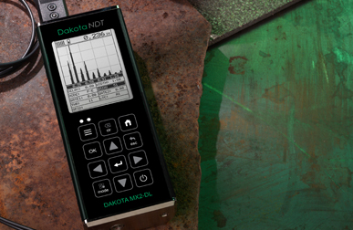

The Dakota MX2-DL Corrosion Thickness Gauge has large, easy to read displays and provides users with A and B-Scan options for accurate interpretation of measurements.
- 要約
-
要約
-
Versatile
Measures uncoated & coated surfaces
Flexible & easy to use, the Dakota MX2-DL Corrosion Thickness gauge doesn’t just measure uncoated surfaces but can also measure coated surfaces. Using Echo Echo ThruPaint™ Mode (EE), coatings up to 2mm (80mils) are ignored.
Powerful
Store up to 4GB of readings and waveforms or B-Scans
Taking 250 readings per second in scan mode, the internal data logger stores up to 4GB of readings together with their waveforms.
Customisable
Choose & customise the reading display
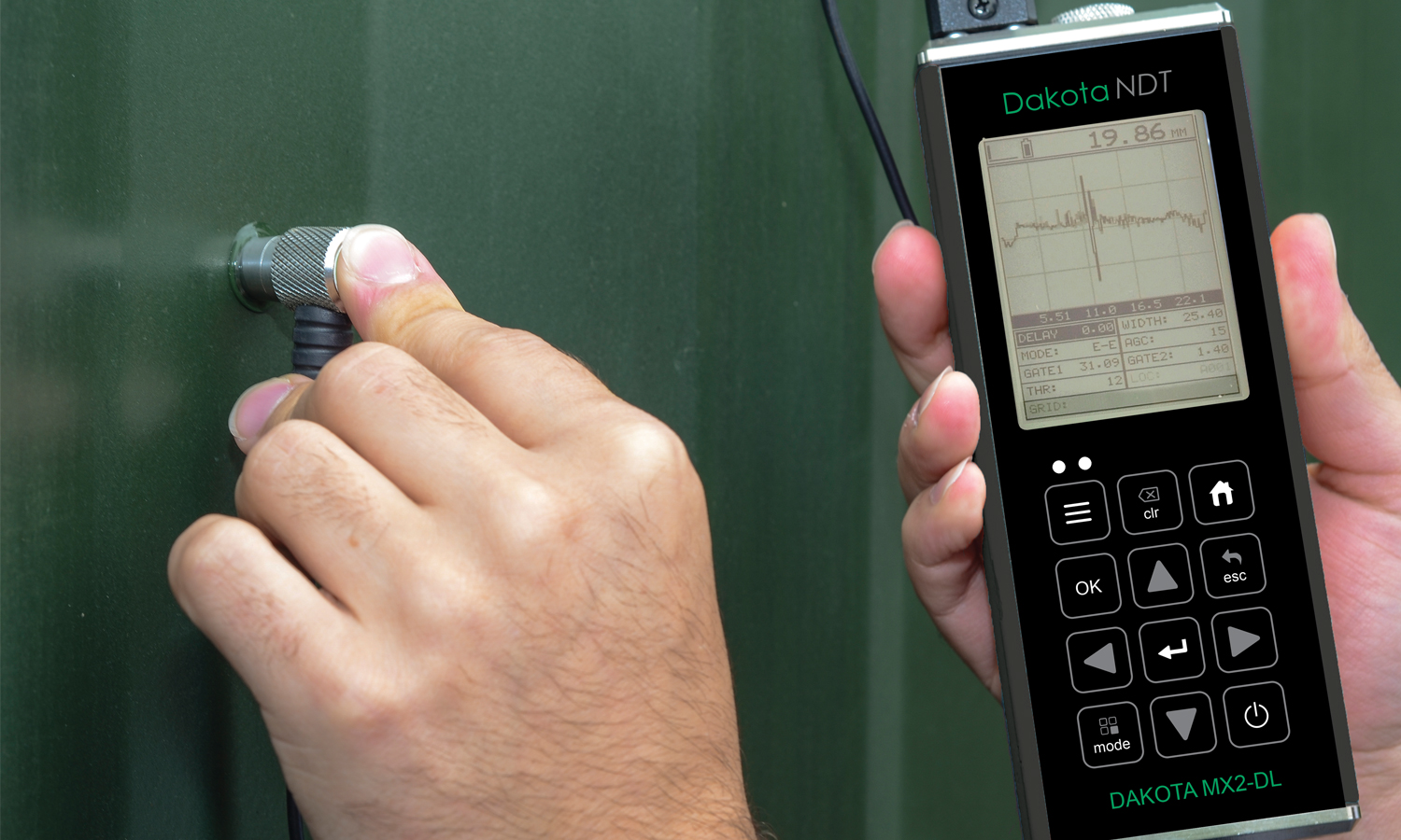
The Dakota MX2-DL ultrasonic thickness gauge has a choice of display modes allowing the user to select the most appropriate for their needs; Readings, B-Scan, B-Scan combined with readings, Scan bar & the A-Scan.
The Dakota MX2-DL Thickness Gauge offers 2D cross sectional block view, providing a graphical representation of a material's thickness, ideal for accurate analysis and identification of pits and corroded areas.
MX2-DL Ultrasonic Thickness Gauge: Taking 250 readings per second in scan mode, the internal data logger stores up to 4GB worth of data together with their waveforms. The MX2-DL Thickness Gauge also features an A-Scan display, allowing users to fully interpret and control measurement readings. The user can select to view either the full waveform (RF) or the rectified waveform (RECT) showing either the positive or the negative cycle of the full waveform.
-
- 特長
-
特長
Dakota MX2-DL Corrosion Thickness Gauge
Support & Resources
Transducer Options
A wide range of Corrosion Thickness Transducers available.
DakMaster™
From inspection to professional reports at the click of a button.
Features Explained
Repeatability / Stability Indicator
Consisting of 6 vertical bars, when all the bars are fully illuminated and the last digit on the digital thickness value is stable, the gauge is reliably measuring the material thickness.
High Speed Scan with Minimum Thickness Display
By significantly increasing the measurement refresh rate this mode allows the user to make scanned passes over the test material. The smallest thickness value is held in memory and displayed when scanning is complete. This feature can also be used in conjunction with the minimum & maximum limit alarm feature (model dependant).
Differential Mode
Once a user defined nominal thickness value has been set, the gauge will display the +/- thickness difference from the nominal value entered.
Limit Alarm Mode
The user can define minimum and maximum thickness limits. If the measurement falls outside the upper or lower limit a red LED will light and the beeper sounds. A green LED will light to indicate an acceptable thickness.
V-Path Correction
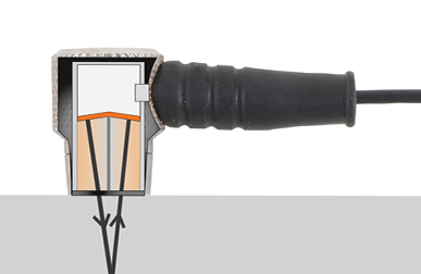
Dual element transducers consist of a probe with two crystals (one to transmit and one to receive the sound pulse). The crystals are separated by an acoustic barrier - generating a 'V-shaped' sound path as the sound travels from one element to the other. This path is slightly longer than the direct path therefore V-path correction is used to calculate the correct thickness.
Measurement Modes Explained
Pulse Echo (PE):
The normal display mode, measures the total thickness from the base of the transducer probe to the material density boundary (typically the back wall). Ideal for pit and flaw detection.
Echo - Echo Mode (EE):
Also known as the ThruPaint™ Mode, EE ignores the coating thickness, displaying the material thickness from the top surface of the material to the material density boundary.
Display Modes Explained
Material Thickness Digits Display:
The standard display on all models, this displays the numerical thickness value in either millimetres (MM) or inches (IN).
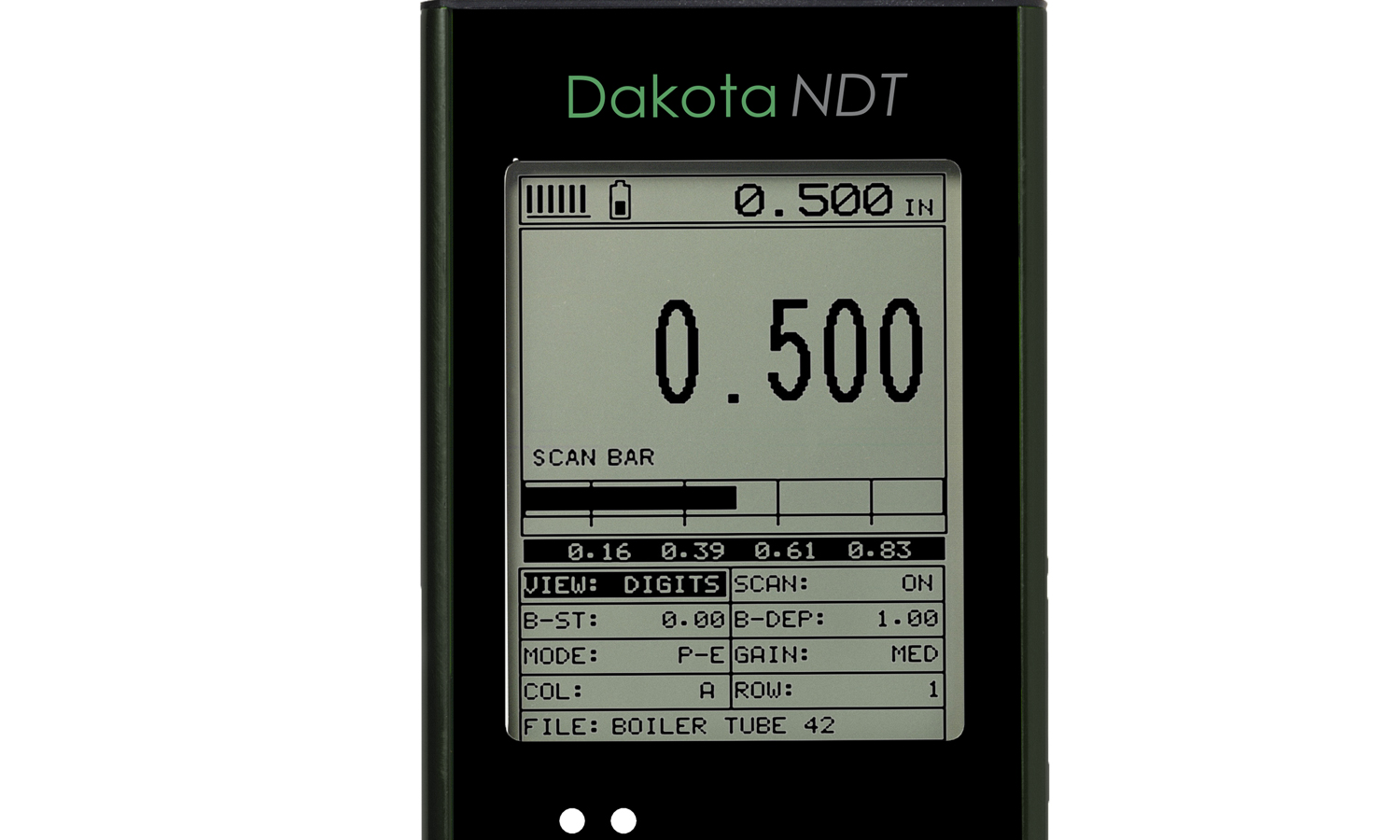
Scan Bar Display:
A linear graphic display which allows users to graphically monitor changes in thickness readings. As the scale range can be adjusted by the user, this display is ideal for observing tiny variations in material thicknesses.
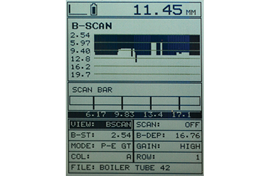
B-Scan Display:
A time based cross sectional 2D block view of the thickness provides a graphical view of the material thickness - ideal for relative depth analysis.
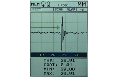
A-Scan Display; Full Wave (RF):*
The A-Scan display shows the sine wave created by the reflected sound, or oscillation, from the material being measured. In RF mode the full wave form is displayed.
A-Scan Display; Rectified (+ or -):*
Users can select to view either the positive or the negative cycle of the full waveform (RF). This rectified (RECT) display shows the amplitude of the echo versus the transit time.
Firmware Upgrades
Regularly checking and updating your firmware is crucial for maintaining performance, and ensuring compatibility with new features.
Make sure your Dakota Corrosion Thickness Gauge is running the latest firmware, select your gauge below.
Dakota Ultrasonic MMX-7
Dakota Ultrasonic MVX
DakotaNDT MX
-
- 製品の特長
-
製品の特長Dakota MX2-DL Corrosion Thickness Gauge
Model MX2-DL 表示モード 厚さ - 数値 Bスキャン(断面図) Bスキャンと数値の組み合わせ スキャンバー Aスキャン 正半波、負半波、全波(RF)Measurement Rate 手動 1秒間に8回読み取りスキャンモード 1秒間に250回読み取りスキャンバー 1秒間に10回読み取分解能 0.01mm (0.001インチ)速度の校正範囲 309.88~18,542m/秒 (0.0122~0.73インチ/マイクロ秒)その他の機能 高速スキャンモード 差分モード 制限値のアラームモード Bスキャン表示速度 1画面あたり10 ~ 200秒測定条件の設定 ユーザーが64件までの測定条件を設定し て、PCに転送可能ゲート • PE:1個、EE:2個、遮断用1個
• しきい値調整可能パルス発振器 Square wave pulser with adjustable pulse width (spike, thin, wide)ゲイン Manual or automatic gain control (AGC) with 40dB range (depending on mode selected)タイミング制御 100MHz 8 bit ultra low power digitizerメモリとデータの記録 • 4GBの内蔵メモリ
• 連続データと表形式データ
• 英数字のバッチID
• OBSTRUCTは、測定不可能な部位を示す
• ビットマップ画像の撮影と画像ビューア探触子の型 二振動子周波数の範囲 1 - 10MHz探触子の認識 手動 - リストから選択Vパス補正(二振動子の路程誤差補正) 自動プローブのゼロ値設定 手動(内蔵ディスク使用)画面 1/8 VGA(グレースケール)
表示域62 x 45.7mm(2.4 x 1.8インチ)画面のリフレッシュレート 25Hz単位(選択可能) mmまたはインチLEDのバックライト オン/オフ/自動繰り返し性と安定性のインジケーター
-
- 仕様
-
Technical SpecificationDakota MX2-DL Corrosion Thickness Gauge
Part Number Description Certificate Z-149-0006 Dakota MX2-DL Thickness Gauge (MVX) 
探触子の型 二振動子型 測定精度 0.1mm (0.01インチ) メモリ容量 4GBの内蔵メモリ 使用温度 -10~60ºC (14~140ºF) データ出力 USB 電源 AA電池3本またはUSB接続 電池の寿命 Alkaline – 35 hrs, Nicad – 10 hrs and NI-MH – 35 hrs 本体重量 383g (13.5 ンス) - 電池を含む 本体寸法 63.5 x 165 x 31.5mm (2.5 x 6.5 x 1.24インチ) 内用品 Unit, Selectable Transducer, Couplant, Manual, Plastic Carrying Case, Certificate of Calibration and AA Batteries. PC Software and Data Transfer Cable included with data logging gauges. 1Measuring range & accuracy depends on material, surface conditions and the transducer selected
2Approximate battery life, when in continuous measurement mode.
● Certificate of Calibration supplied as standard
-
- 適合規格
-
適合規格Dakota MX2-DL Corrosion Thickness Gauge
Factory calibration traceable to NIST & MIL-STD-45662
-
- ダウンロード
-
ダウンロード
-

超音波厚さ計 CG70 取扱説明書
-

超音波厚さ計 CG70 - データシート
-
超音波厚さ計 CG70 - 適合宣言書
- コード番号
-
コード番号Dakota MX2-DL Corrosion Thickness Gauge
-
 Dakota MX2-DL Corrosion Thickness Gauge
- コード番号 : Z-149-0006
Dakota MX2-DL Corrosion Thickness Gauge
The Dakota MX2-DL Corrosion Thickness Gauge has large, easy to read displays and provides users with A and B-Scan options for accurate interpretation of measurements.
Versatile
Measures uncoated & coated surfaces
Flexible & easy to use, the Dakota MX2-DL Corrosion Thickness gauge doesn’t just measure uncoated surfaces but can also measure coated surfaces. Using Echo Echo ThruPaint™ Mode (EE), coatings up to 2mm (80mils) are ignored.
Powerful
Store up to 4GB of readings and waveforms or B-Scans
Taking 250 readings per second in scan mode, the internal data logger stores up to 4GB of readings together with their waveforms.
Customisable
Choose & customise the reading display
The Dakota MX2-DL ultrasonic thickness gauge has a choice of display modes allowing the user to select the most appropriate for their needs; Readings, B-Scan, B-Scan combined with readings, Scan bar & the A-Scan.
要約

Dakota MX2-DL Corrosion Thickness Gauge
The Dakota MX2-DL Thickness Gauge offers 2D cross sectional block view, providing a graphical representation of a material's thickness, ideal for accurate analysis and identification of pits and corroded areas.
MX2-DL Ultrasonic Thickness Gauge: Taking 250 readings per second in scan mode, the internal data logger stores up to 4GB worth of data together with their waveforms. The MX2-DL Thickness Gauge also features an A-Scan display, allowing users to fully interpret and control measurement readings. The user can select to view either the full waveform (RF) or the rectified waveform (RECT) showing either the positive or the negative cycle of the full waveform.
特長
Dakota MX2-DL Corrosion Thickness Gauge
Support & Resources
Transducer Options
A wide range of Corrosion Thickness Transducers available.
DakMaster™
From inspection to professional reports at the click of a button.
Features Explained
Repeatability / Stability Indicator
Consisting of 6 vertical bars, when all the bars are fully illuminated and the last digit on the digital thickness value is stable, the gauge is reliably measuring the material thickness.
High Speed Scan with Minimum Thickness Display
By significantly increasing the measurement refresh rate this mode allows the user to make scanned passes over the test material. The smallest thickness value is held in memory and displayed when scanning is complete. This feature can also be used in conjunction with the minimum & maximum limit alarm feature (model dependant).
Differential Mode
Once a user defined nominal thickness value has been set, the gauge will display the +/- thickness difference from the nominal value entered.
Limit Alarm Mode
The user can define minimum and maximum thickness limits. If the measurement falls outside the upper or lower limit a red LED will light and the beeper sounds. A green LED will light to indicate an acceptable thickness.
V-Path Correction
Dual element transducers consist of a probe with two crystals (one to transmit and one to receive the sound pulse). The crystals are separated by an acoustic barrier - generating a 'V-shaped' sound path as the sound travels from one element to the other. This path is slightly longer than the direct path therefore V-path correction is used to calculate the correct thickness.
Measurement Modes Explained
Pulse Echo (PE):
The normal display mode, measures the total thickness from the base of the transducer probe to the material density boundary (typically the back wall). Ideal for pit and flaw detection.
Echo - Echo Mode (EE):
Also known as the ThruPaint™ Mode, EE ignores the coating thickness, displaying the material thickness from the top surface of the material to the material density boundary.
Display Modes Explained
Material Thickness Digits Display:
The standard display on all models, this displays the numerical thickness value in either millimetres (MM) or inches (IN).
Scan Bar Display:
A linear graphic display which allows users to graphically monitor changes in thickness readings. As the scale range can be adjusted by the user, this display is ideal for observing tiny variations in material thicknesses.
B-Scan Display:
A time based cross sectional 2D block view of the thickness provides a graphical view of the material thickness - ideal for relative depth analysis.
A-Scan Display; Full Wave (RF):*
The A-Scan display shows the sine wave created by the reflected sound, or oscillation, from the material being measured. In RF mode the full wave form is displayed.
A-Scan Display; Rectified (+ or -):*
Users can select to view either the positive or the negative cycle of the full waveform (RF). This rectified (RECT) display shows the amplitude of the echo versus the transit time.
Firmware Upgrades
Regularly checking and updating your firmware is crucial for maintaining performance, and ensuring compatibility with new features.
Make sure your Dakota Corrosion Thickness Gauge is running the latest firmware, select your gauge below.
Dakota Ultrasonic MMX-7
Dakota Ultrasonic MVX
DakotaNDT MX
製品の特長Dakota MX2-DL Corrosion Thickness GaugeModel MX2-DL 表示モード 厚さ - 数値 Bスキャン(断面図) Bスキャンと数値の組み合わせ スキャンバー Aスキャン 正半波、負半波、全波(RF)Measurement Rate 手動 1秒間に8回読み取りスキャンモード 1秒間に250回読み取りスキャンバー 1秒間に10回読み取分解能 0.01mm (0.001インチ)速度の校正範囲 309.88~18,542m/秒 (0.0122~0.73インチ/マイクロ秒)その他の機能 高速スキャンモード 差分モード 制限値のアラームモード Bスキャン表示速度 1画面あたり10 ~ 200秒測定条件の設定 ユーザーが64件までの測定条件を設定し て、PCに転送可能ゲート • PE:1個、EE:2個、遮断用1個
• しきい値調整可能パルス発振器 Square wave pulser with adjustable pulse width (spike, thin, wide)ゲイン Manual or automatic gain control (AGC) with 40dB range (depending on mode selected)タイミング制御 100MHz 8 bit ultra low power digitizerメモリとデータの記録 • 4GBの内蔵メモリ
• 連続データと表形式データ
• 英数字のバッチID
• OBSTRUCTは、測定不可能な部位を示す
• ビットマップ画像の撮影と画像ビューア探触子の型 二振動子周波数の範囲 1 - 10MHz探触子の認識 手動 - リストから選択Vパス補正(二振動子の路程誤差補正) 自動プローブのゼロ値設定 手動(内蔵ディスク使用)画面 1/8 VGA(グレースケール)
表示域62 x 45.7mm(2.4 x 1.8インチ)画面のリフレッシュレート 25Hz単位(選択可能) mmまたはインチLEDのバックライト オン/オフ/自動繰り返し性と安定性のインジケーター Technical SpecificationDakota MX2-DL Corrosion Thickness GaugePart Number Description Certificate Z-149-0006 Dakota MX2-DL Thickness Gauge (MVX) 探触子の型 二振動子型 測定精度 0.1mm (0.01インチ) メモリ容量 4GBの内蔵メモリ 使用温度 -10~60ºC (14~140ºF) データ出力 USB 電源 AA電池3本またはUSB接続 電池の寿命 Alkaline – 35 hrs, Nicad – 10 hrs and NI-MH – 35 hrs 本体重量 383g (13.5 ンス) - 電池を含む 本体寸法 63.5 x 165 x 31.5mm (2.5 x 6.5 x 1.24インチ) 内用品 Unit, Selectable Transducer, Couplant, Manual, Plastic Carrying Case, Certificate of Calibration and AA Batteries. PC Software and Data Transfer Cable included with data logging gauges. 1Measuring range & accuracy depends on material, surface conditions and the transducer selected
2Approximate battery life, when in continuous measurement mode.
● Certificate of Calibration supplied as standard -
-