

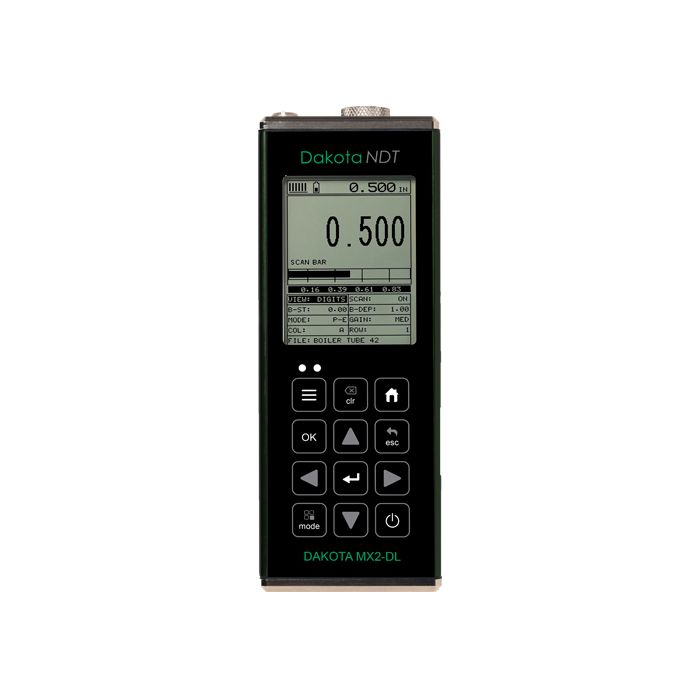
Dakota MX2-DL Corrosion Thickness Gauge
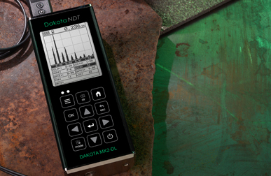

The Dakota MX2-DL Corrosion Thickness Gauge has large, easy to read displays and provides users with A and B-Scan options for accurate interpretation of measurements.
- Sommario
-
Sommario
-
Versatile
Measures uncoated & coated surfaces
Flexible & easy to use, the Dakota MX2-DL Corrosion Thickness gauge doesn’t just measure uncoated surfaces but can also measure coated surfaces. Using Echo Echo ThruPaint™ Mode (EE), coatings up to 2mm (80mils) are ignored.
Powerful
Store up to 4GB of readings and waveforms or B-Scans
Taking 250 readings per second in scan mode, the internal data logger stores up to 4GB of readings together with their waveforms.
Customisable
Choose & customise the reading display
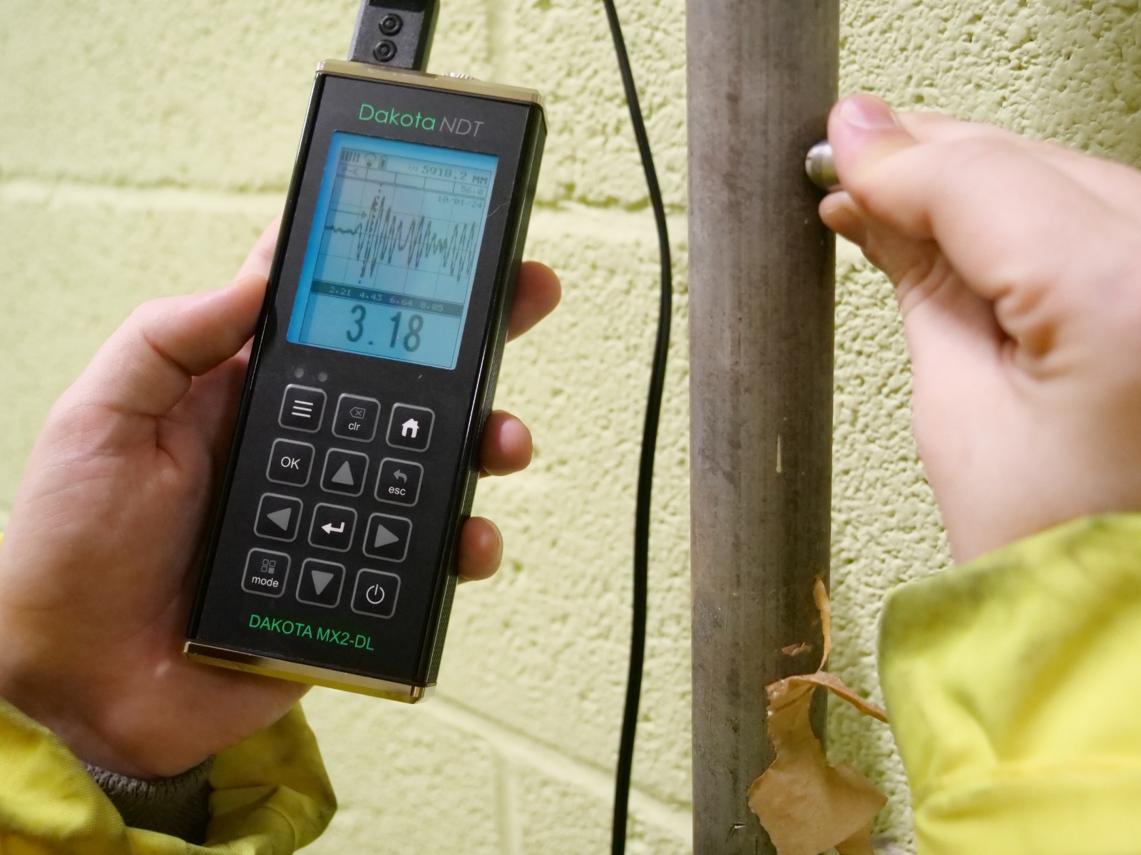
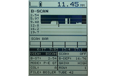
The Dakota MX2-DL ultrasonic thickness gauge has a choice of display modes allowing the user to select the most appropriate for their needs; Readings, B-Scan, B-Scan combined with readings, Scan bar & the A-Scan.
The Dakota MX2-DL Thickness Gauge offers 2D cross sectional block view, providing a graphical representation of a material's thickness, ideal for accurate analysis and identification of pits and corroded areas.
MX2-DL Ultrasonic Thickness Gauge: Taking 250 readings per second in scan mode, the internal data logger stores up to 4GB worth of data together with their waveforms. The MX2-DL Thickness Gauge also features an A-Scan display, allowing users to fully interpret and control measurement readings. The user can select to view either the full waveform (RF) or the rectified waveform (RECT) showing either the positive or the negative cycle of the full waveform.
-
- Caratteristiche principali
-
Caratteristiche principali
Dakota MX2-DL Corrosion Thickness Gauge
Support & Resources
Transducer Options
A wide range of Corrosion Thickness Transducers available.
DakMaster™
From inspection to professional reports at the click of a button.
Features Explained
Repeatability / Stability Indicator
Consisting of 6 vertical bars, when all the bars are fully illuminated and the last digit on the digital thickness value is stable, the gauge is reliably measuring the material thickness.
High Speed Scan with Minimum Thickness Display
By significantly increasing the measurement refresh rate this mode allows the user to make scanned passes over the test material. The smallest thickness value is held in memory and displayed when scanning is complete. This feature can also be used in conjunction with the minimum & maximum limit alarm feature (model dependant).
Differential Mode
Once a user defined nominal thickness value has been set, the gauge will display the +/- thickness difference from the nominal value entered.
Limit Alarm Mode
The user can define minimum and maximum thickness limits. If the measurement falls outside the upper or lower limit a red LED will light and the beeper sounds. A green LED will light to indicate an acceptable thickness.
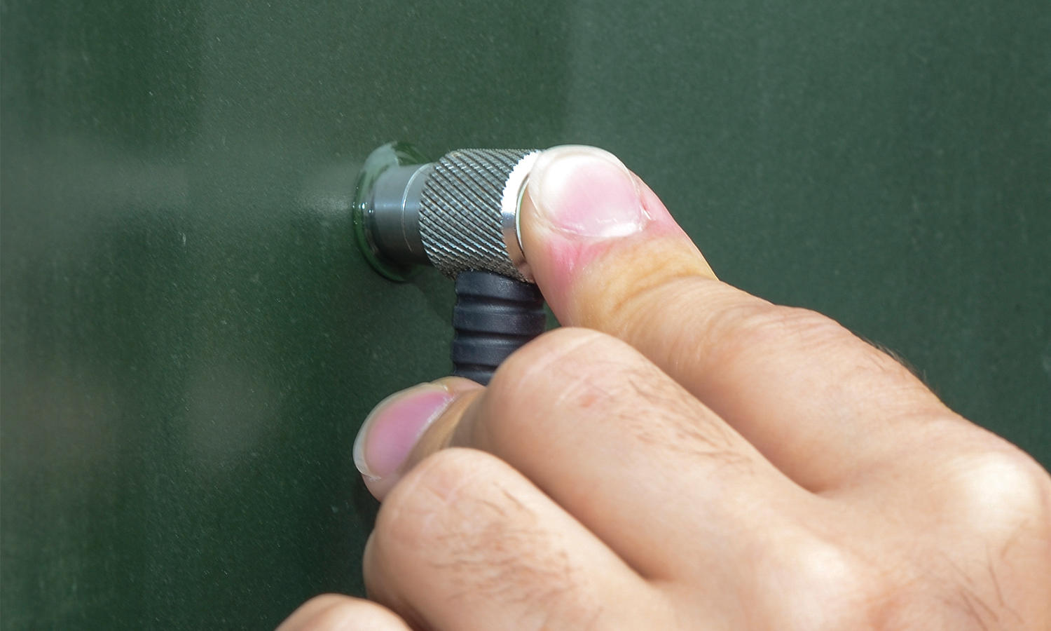
V-Path Correction
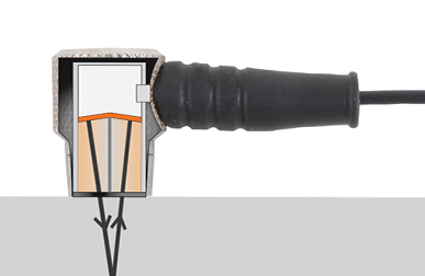
Dual element transducers consist of a probe with two crystals (one to transmit and one to receive the sound pulse). The crystals are separated by an acoustic barrier - generating a 'V-shaped' sound path as the sound travels from one element to the other. This path is slightly longer than the direct path therefore V-path correction is used to calculate the correct thickness.
Measurement Modes Explained
Pulse Echo (PE):
The normal display mode, measures the total thickness from the base of the transducer probe to the material density boundary (typically the back wall). Ideal for pit and flaw detection.
Echo - Echo Mode (EE):
Also known as the ThruPaint™ Mode, EE ignores the coating thickness, displaying the material thickness from the top surface of the material to the material density boundary.
Display Modes Explained
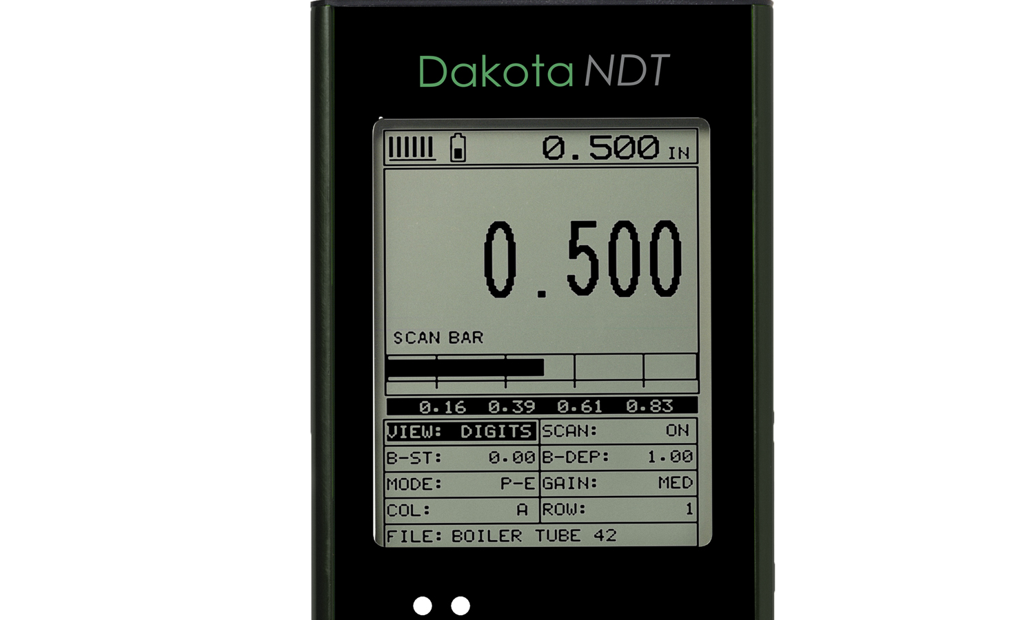
Material Thickness Digits Display:
The standard display on all models, this displays the numerical thickness value in either millimetres (MM) or inches (IN).
Scan Bar Display:
A linear graphic display which allows users to graphically monitor changes in thickness readings. As the scale range can be adjusted by the user, this display is ideal for observing tiny variations in material thicknesses.
B-Scan Display:
A time based cross sectional 2D block view of the thickness provides a graphical view of the material thickness - ideal for relative depth analysis.
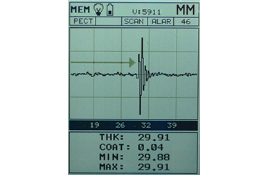
A-Scan Display; Full Wave (RF):*
The A-Scan display shows the sine wave created by the reflected sound, or oscillation, from the material being measured. In RF mode the full wave form is displayed.
A-Scan Display; Rectified (+ or -):*
Users can select to view either the positive or the negative cycle of the full waveform (RF). This rectified (RECT) display shows the amplitude of the echo versus the transit time.
Firmware Upgrades
Regularly checking and updating your firmware is crucial for maintaining performance, and ensuring compatibility with new features.
Make sure your Dakota Corrosion Thickness Gauge is running the latest firmware, select your gauge below.
Dakota Ultrasonic MMX-7
Dakota Ultrasonic MVX
DakotaNDT MX
-
- Caratteristiche del Prodotto
-
Caratteristiche del ProdottoDakota MX2-DL Corrosion Thickness Gauge
Model MX2-DL Modalità di visualizzazione Visualizzazione valori di spessore del materiale Vista sezione incrociata B-Scan Vista combinata B-Scan e valori Vista a barre di scansione Vista A-Scan + rettificato, - rettificato, forma d'onda completa (RF)Measurement Rate Manuale 8 letture al secondoModalità scansione 250 letture al secondoVista a barre di scansione 10 letture al secondoRisoluzione di misurazione 0,01mm (0,001”)Range di calibrazione velocità del suono 309,88 - 18.542 m/s (0,0122 - 0,7300 in/μs)Caratteristiche aggiuntive Modalità scansione ad alta velocità Modalità differenziale Modalità avviso di superamento limite Velocità di visualizzazione B-Scan 10 - 200 secondi per schermataImpostazioni di calibrazione 64 impostazioni definibili dall’utente, trasferibili a e da un archivio su PCPorte • PE: 1 porta; EE: 2 porte, 1 porta con trattenimento
• Soglia regolabileTipo di impulsatore Square wave pulser with adjustable pulse width (spike, thin, wide)Guadagno Manual or automatic gain control (AGC) with 40dB range (depending on mode selected)Temporizzazione 100MHz 8 bit ultra low power digitizerMemoria e registrazione dati • 4 GB di memoria interna
• Registrazione sequenziale e a griglia
• Identificazione batch alfanumerica
• OBSTRUCT indica le posizioni inaccessibili
• Acquisizione di grafica bitmap e visualizzatore immaginiTipo di sonda trasduttore Elemento doppioGamma di frequenza trasduttore 1 - 10MHzRiconoscimento trasduttore Manuale - selezionabile da un elencoCorrezione errori percorso a V/percorso doppio AutomaticaSonda Zero Manuale (tramite disco sonda integrato)Display 1/8 VGA (scala di grigi) area di visualizzazione
62 x 45,7 mm (2,4 x 1,8”)Frequenza di aggiornamento display 25HzUnità (selezionabili) mm o polliciRetroilluminazione a LED Accesa / spenta / automaticaIndicatore di ripetibilità/stabilità
-
- Dati tecnici
-
Technical SpecificationDakota MX2-DL Corrosion Thickness Gauge
Part Number Description Certificate Z-149-0006 Dakota MX2-DL Thickness Gauge (MVX) 
Tipo di sonda trasduttore Elemento doppio Precisione di misurazione 0,01mm (0.001”) Memoria 4 GB di memoria interna Temperatura di esercizio -10 a 60ºC (14 a 140ºF) Uscita dati USB Alimentazione 3 batterie AA e USB Durata batteria Alcaline – 35 ore, nichel-cadmio – 10 ore e NI-MH – 35 ore Peso calibro 383g (13,5oz) - incluse le batterie Dimensioni calibro 63,5 x 165 x 31,5mm (2,5 x 6,5 x 1,24”) Lista di imballaggio Unit, Selectable Transducer, Couplant, Manual, Plastic Carrying Case, Certificate of Calibration and AA Batteries. PC Software and Data Transfer Cable included with data logging gauges. 1Measuring range & accuracy depends on material, surface conditions and the transducer selected
2Approximate battery life, when in continuous measurement mode.
● Certificate of Calibration supplied as standard
-
- Standard
-
StandardDakota MX2-DL Corrosion Thickness Gauge
Factory calibration traceable to NIST & MIL-STD-45662
-
- Download
-
Download
-

Dakota MX2-DL Thickness Gauge (MVX) Instruction Manual
-

Dakota MX2-DL Thickness Gauge (MVX) Datasheet
- Codice articolo
-
Codice articoloDakota MX2-DL Corrosion Thickness Gauge
-
 Dakota MX2-DL Corrosion Thickness Gauge
- Codice articolo : Z-149-0006
Dakota MX2-DL Corrosion Thickness Gauge
The Dakota MX2-DL Corrosion Thickness Gauge has large, easy to read displays and provides users with A and B-Scan options for accurate interpretation of measurements.
Versatile
Measures uncoated & coated surfaces
Flexible & easy to use, the Dakota MX2-DL Corrosion Thickness gauge doesn’t just measure uncoated surfaces but can also measure coated surfaces. Using Echo Echo ThruPaint™ Mode (EE), coatings up to 2mm (80mils) are ignored.
Powerful
Store up to 4GB of readings and waveforms or B-Scans
Taking 250 readings per second in scan mode, the internal data logger stores up to 4GB of readings together with their waveforms.
Customisable
Choose & customise the reading display
The Dakota MX2-DL ultrasonic thickness gauge has a choice of display modes allowing the user to select the most appropriate for their needs; Readings, B-Scan, B-Scan combined with readings, Scan bar & the A-Scan.
Sommario
Dakota MX2-DL Corrosion Thickness Gauge
The Dakota MX2-DL Thickness Gauge offers 2D cross sectional block view, providing a graphical representation of a material's thickness, ideal for accurate analysis and identification of pits and corroded areas.
MX2-DL Ultrasonic Thickness Gauge: Taking 250 readings per second in scan mode, the internal data logger stores up to 4GB worth of data together with their waveforms. The MX2-DL Thickness Gauge also features an A-Scan display, allowing users to fully interpret and control measurement readings. The user can select to view either the full waveform (RF) or the rectified waveform (RECT) showing either the positive or the negative cycle of the full waveform.
Download-
Dakota MX2-DL Thickness Gauge (MVX) Instruction Manual
-
Dakota MX2-DL Thickness Gauge (MVX) Datasheet
Caratteristiche principali
Dakota MX2-DL Corrosion Thickness Gauge
Support & Resources
Transducer Options
A wide range of Corrosion Thickness Transducers available.
DakMaster™
From inspection to professional reports at the click of a button.
Features Explained
Repeatability / Stability Indicator
Consisting of 6 vertical bars, when all the bars are fully illuminated and the last digit on the digital thickness value is stable, the gauge is reliably measuring the material thickness.
High Speed Scan with Minimum Thickness Display
By significantly increasing the measurement refresh rate this mode allows the user to make scanned passes over the test material. The smallest thickness value is held in memory and displayed when scanning is complete. This feature can also be used in conjunction with the minimum & maximum limit alarm feature (model dependant).
Differential Mode
Once a user defined nominal thickness value has been set, the gauge will display the +/- thickness difference from the nominal value entered.
Limit Alarm Mode
The user can define minimum and maximum thickness limits. If the measurement falls outside the upper or lower limit a red LED will light and the beeper sounds. A green LED will light to indicate an acceptable thickness.
V-Path Correction
Dual element transducers consist of a probe with two crystals (one to transmit and one to receive the sound pulse). The crystals are separated by an acoustic barrier - generating a 'V-shaped' sound path as the sound travels from one element to the other. This path is slightly longer than the direct path therefore V-path correction is used to calculate the correct thickness.
Measurement Modes Explained
Pulse Echo (PE):
The normal display mode, measures the total thickness from the base of the transducer probe to the material density boundary (typically the back wall). Ideal for pit and flaw detection.
Echo - Echo Mode (EE):
Also known as the ThruPaint™ Mode, EE ignores the coating thickness, displaying the material thickness from the top surface of the material to the material density boundary.
Display Modes Explained
Material Thickness Digits Display:
The standard display on all models, this displays the numerical thickness value in either millimetres (MM) or inches (IN).
Scan Bar Display:
A linear graphic display which allows users to graphically monitor changes in thickness readings. As the scale range can be adjusted by the user, this display is ideal for observing tiny variations in material thicknesses.
B-Scan Display:
A time based cross sectional 2D block view of the thickness provides a graphical view of the material thickness - ideal for relative depth analysis.
A-Scan Display; Full Wave (RF):*
The A-Scan display shows the sine wave created by the reflected sound, or oscillation, from the material being measured. In RF mode the full wave form is displayed.
A-Scan Display; Rectified (+ or -):*
Users can select to view either the positive or the negative cycle of the full waveform (RF). This rectified (RECT) display shows the amplitude of the echo versus the transit time.
Firmware Upgrades
Regularly checking and updating your firmware is crucial for maintaining performance, and ensuring compatibility with new features.
Make sure your Dakota Corrosion Thickness Gauge is running the latest firmware, select your gauge below.
Dakota Ultrasonic MMX-7
Dakota Ultrasonic MVX
DakotaNDT MX
Caratteristiche del ProdottoDakota MX2-DL Corrosion Thickness GaugeModel MX2-DL Modalità di visualizzazione Visualizzazione valori di spessore del materiale Vista sezione incrociata B-Scan Vista combinata B-Scan e valori Vista a barre di scansione Vista A-Scan + rettificato, - rettificato, forma d'onda completa (RF)Measurement Rate Manuale 8 letture al secondoModalità scansione 250 letture al secondoVista a barre di scansione 10 letture al secondoRisoluzione di misurazione 0,01mm (0,001”)Range di calibrazione velocità del suono 309,88 - 18.542 m/s (0,0122 - 0,7300 in/μs)Caratteristiche aggiuntive Modalità scansione ad alta velocità Modalità differenziale Modalità avviso di superamento limite Velocità di visualizzazione B-Scan 10 - 200 secondi per schermataImpostazioni di calibrazione 64 impostazioni definibili dall’utente, trasferibili a e da un archivio su PCPorte • PE: 1 porta; EE: 2 porte, 1 porta con trattenimento
• Soglia regolabileTipo di impulsatore Square wave pulser with adjustable pulse width (spike, thin, wide)Guadagno Manual or automatic gain control (AGC) with 40dB range (depending on mode selected)Temporizzazione 100MHz 8 bit ultra low power digitizerMemoria e registrazione dati • 4 GB di memoria interna
• Registrazione sequenziale e a griglia
• Identificazione batch alfanumerica
• OBSTRUCT indica le posizioni inaccessibili
• Acquisizione di grafica bitmap e visualizzatore immaginiTipo di sonda trasduttore Elemento doppioGamma di frequenza trasduttore 1 - 10MHzRiconoscimento trasduttore Manuale - selezionabile da un elencoCorrezione errori percorso a V/percorso doppio AutomaticaSonda Zero Manuale (tramite disco sonda integrato)Display 1/8 VGA (scala di grigi) area di visualizzazione
62 x 45,7 mm (2,4 x 1,8”)Frequenza di aggiornamento display 25HzUnità (selezionabili) mm o polliciRetroilluminazione a LED Accesa / spenta / automaticaIndicatore di ripetibilità/stabilità Technical SpecificationDakota MX2-DL Corrosion Thickness GaugePart Number Description Certificate Z-149-0006 Dakota MX2-DL Thickness Gauge (MVX) Tipo di sonda trasduttore Elemento doppio Precisione di misurazione 0,01mm (0.001”) Memoria 4 GB di memoria interna Temperatura di esercizio -10 a 60ºC (14 a 140ºF) Uscita dati USB Alimentazione 3 batterie AA e USB Durata batteria Alcaline – 35 ore, nichel-cadmio – 10 ore e NI-MH – 35 ore Peso calibro 383g (13,5oz) - incluse le batterie Dimensioni calibro 63,5 x 165 x 31,5mm (2,5 x 6,5 x 1,24”) Lista di imballaggio Unit, Selectable Transducer, Couplant, Manual, Plastic Carrying Case, Certificate of Calibration and AA Batteries. PC Software and Data Transfer Cable included with data logging gauges. 1Measuring range & accuracy depends on material, surface conditions and the transducer selected
2Approximate battery life, when in continuous measurement mode.
● Certificate of Calibration supplied as standardStandardDakota MX2-DL Corrosion Thickness GaugeFactory calibration traceable to NIST & MIL-STD-45662
-
-