Measurement Modes
We have discussed transmitted sound and received sound, we have also illustrated short pulses of sound. Combining these two thoughts has resulted in the transmitted and received sound being known as pulse and echo.
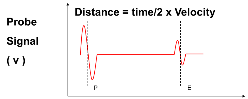
P-E Mode
The first mode we will discuss is known as the Pulse-Echo or P-E mode. This is the simplest and most common measurement mode used in thickness and flaw detection measurement. The gauge uses the time from the transmission of the initial pulse to the receipt of the first echo to calculate the thickness of the material.
All the gauges in the Dakota Material Thickness Gauge (CX) range use P-E as one of their measurement modes. P-E is the only measurement mode the Dakota CX2 uses.
I-E Mode
When measuring thin materials, a delay line is normally used. Typically, a delay line is made of plastic and screws into the front of the transducer.
The purpose of the delay line is, as the name suggests, to delay the sound wave to enable the measurement of thin materials. As the materials are so thin, the returning echo would arrive whilst the initial pulse is still ringing. This would mean that the gauge may not be able to give a thickness reading as it would be unable to differentiate between pulse and echo.

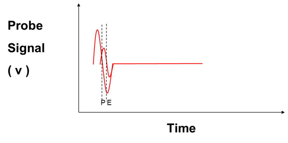
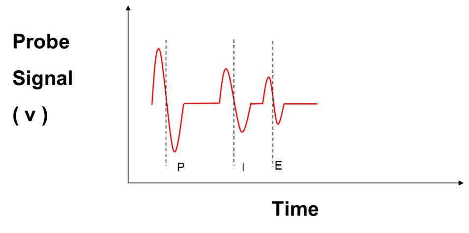
By introducing a delay line, there will now be an initial pulse, an echo, from the interface of delay line and sample and from the back wall of the sample. This gives us our second measurement mode, the Interface-Echo or I-E mode.

The speed of sound in the plastic delay line will be considerably slower than the speed of sound in most metals - approximately half of that in steel. This will have the effect of “spacing out” the pulse and echo signals, enabling the gauge to obtain a reading.
The Dakota Precision Thickness (PCX) Gauges use this mode to measure thin substrates.
E-E Mode
If we follow the path of the sound in the substrate, the next measurement mode would give us the possibility to measure between two consecutive back wall echoes. This mode is known as Echo-Echo or E-E mode.
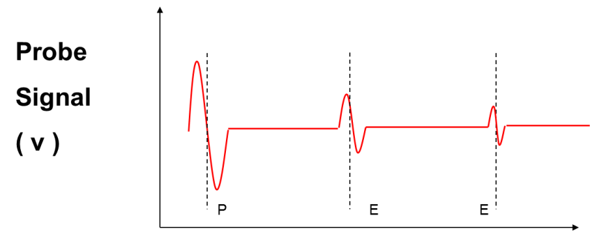
As the sound path between the two echoes is totally within the substrate (see Figure 19) then the thickness measurement is unaffected by anything on the substrate surface. This gives us our ThruPaint™ measurement capability.

Echo–Echo or E-E is a measurement mode available on the Dakota CX4, 6 and 8 models.
E-Ev Mode

If the method being used is the E-Ev mode, then the gauge measures the time between the first two back wall echoes and then, as a check, measures the time between the 2nd and 3rd back wall echo to confirm the reading.
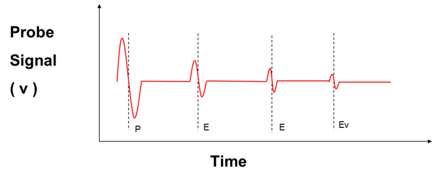
Looking at Figure 21, we can see why it is sometimes called “triple echo”. More technically complex gauges.