How to avoid common errors made during grid thickness measurement
How to avoid common errors made during grid thickness measurement
With many types of thickness gauges on the market, it is vital to understand the capability differences. It is well known individual gauge performance and build quality have significant impact on the resulting measurement and probability of detection (POD).
Thickness gauge performance is a critically important part of the selection process.This application note will highlight the potential errors of transducer placement, and the importance of scanning the surrounding area. The impact of scan speed on visibility and detection of wall loss by corrosion to reduce critical structural failures formed during the corrosion process.
The Grid
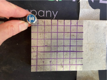
The standard practice is to draw a grid on a part to be evaluated. The transducer is placed in the grid square and thickness is recorded.
Below is a good example of this practice.
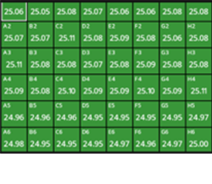
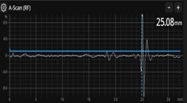
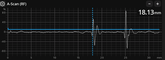
The Grid highlights solid numbers, A-Scan display shows no issues.
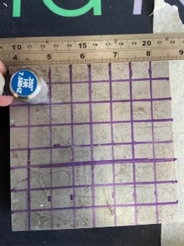
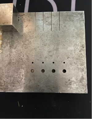
Yet, as we can see below the reverse of the block has several flat bottomed holes in the lower section of the sample. These have been missed. By both Digital and A-Scan Gauge. All gauges used would be expected to see these flat bottom holes.
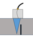
The transmitted signal from the dual transducer has missed the defect, the Transducer crystal and subsequent V path created by the transducer have diverted the focus and prevent total field coverage below the transducer.
This is a vital observation and one with far reaching and critical potential impacts. This lack of coverage from the transducer placement location avoids and will miss the critical indications.
Improved grid area coverage by transducer manipulation
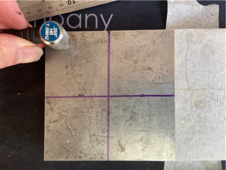
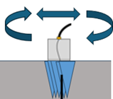
When measuring inside a marked grid and taking a measurement, it is good practice to ensure complete measurement confidence is possible by scanning the surrounding region. Gentle movement of the transducer around the region of the grid.
This movement will pick up potential variations. Enabling the user to identify and note the true minimum thickness and their critical nature.
Please Note – It is vitally important to understand, a gauge with inferior performance, is slower to react when scanning, and as a result has a significant potential to miss indications regardless of operational manipulations.Poor performance gauges being to slow to react will not highlight issues to the inspector and is one of the biggest causes of inspection error and critical asset failure.
Regional improvement, traceability and identification.
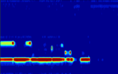
Gauges with A-Scan and B-Scan recording features offer additional advantages.Fully traceable scan data, with ability to record over a larger area. Identify any potential wall loss and record minimum thickness. Offering a time saving opportunity in both marking out, and inspection recording time.