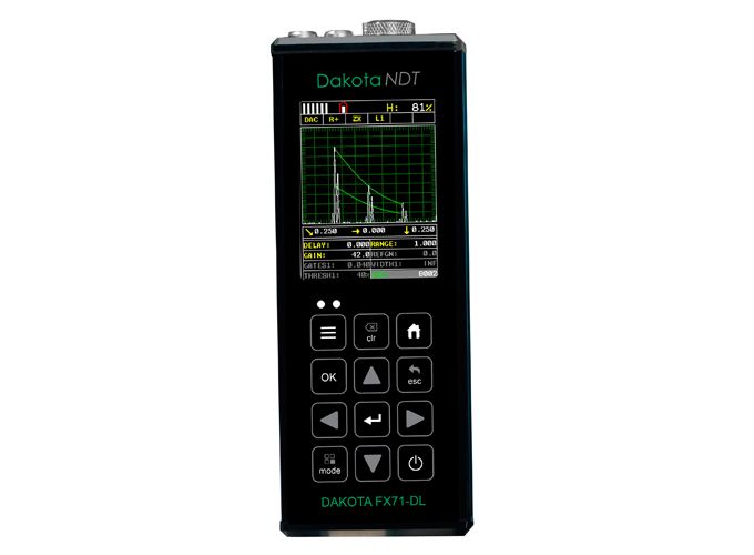
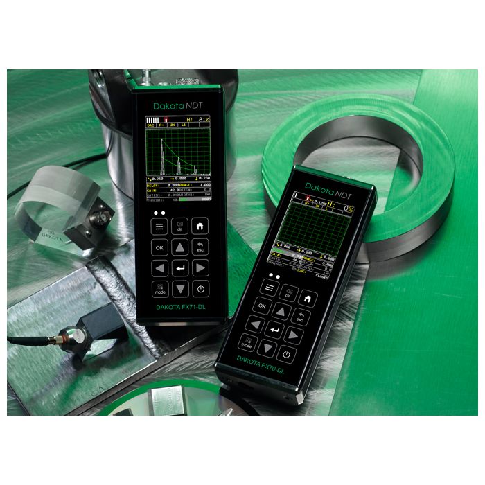
Dakota FX71-DL Flaw Detector (DFX-7)
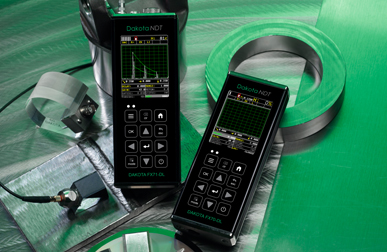
The hand-held Dakota FX71-DL Flaw Detector range combines state-of-the-art flaw detection with advanced material thickness capabilities.
- Summary
-
Summary
-
Versatile
Two gauges in one
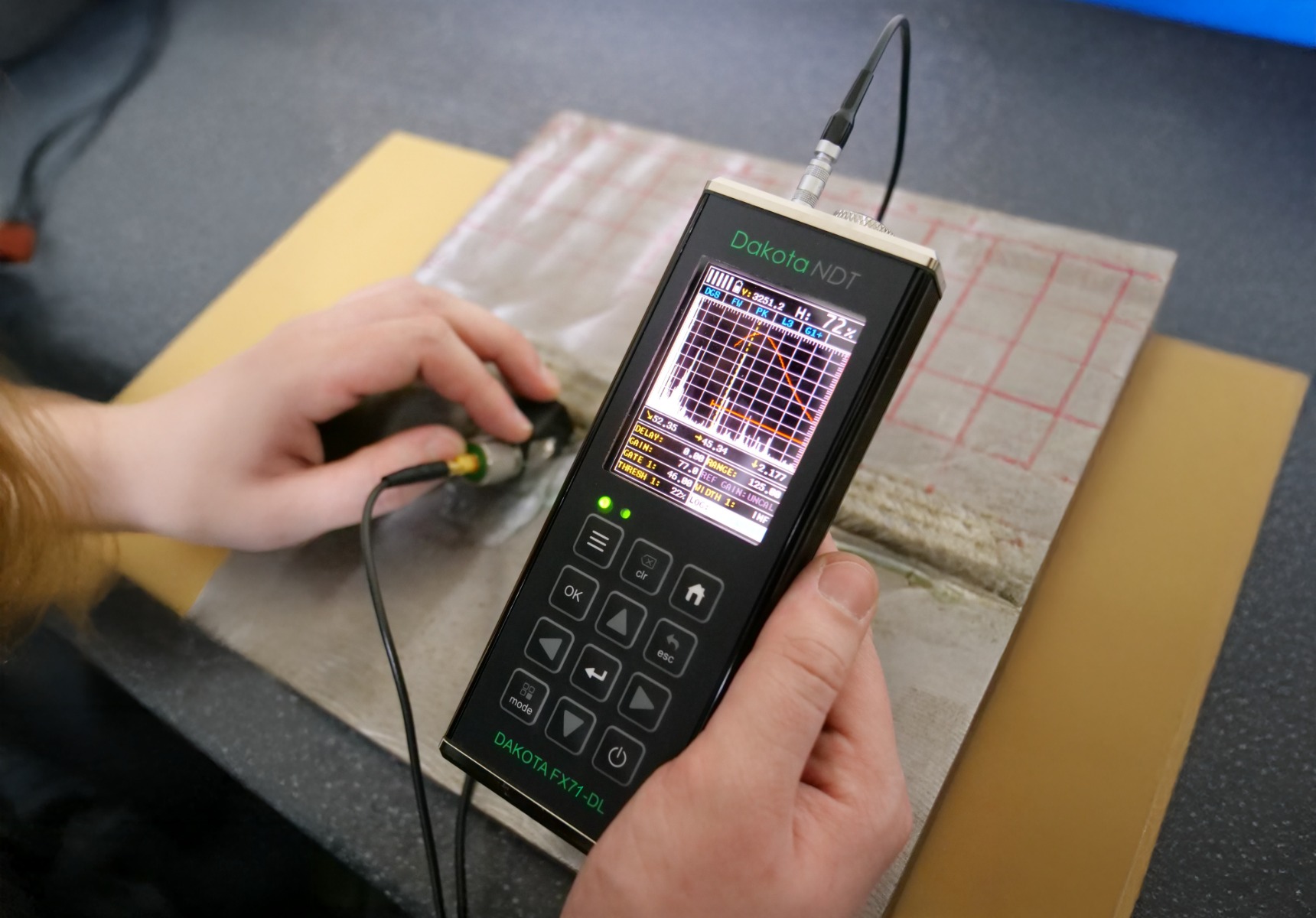
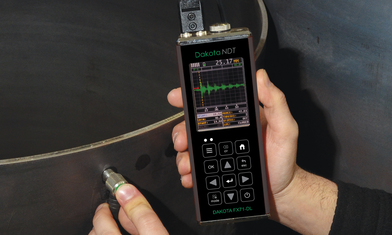
The Dakota FX71-DL Flaw Detector series has two functions, a thickness gauge and a flaw detector. When the Dakota FX71-DL Flaw Detector is set to thickness gauge it has the ability to measure coatings and material thickness simultaneously. When set to flaw detector the gauge has the ability to detect the size and position of flaws and to differentiate between flaw types in various materials and welded joints.
Intelligent
User definable limits for pass/fail indication
Set hi/lo limits for pass/fail indication with audible warnings and built-in differential mode for quality control inspections.
Powerful
Store each measurement for further analysis
Up to 4GB of readings can be saved into the gauge memory as each measurement is taken, which can be downloaded later into an inspection application or into DakMaster™ Software for further analysis and reporting.
Customisable
Customisable tool kits and reading display
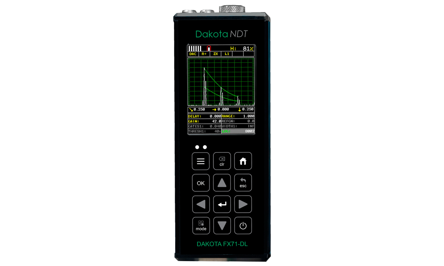
The Dakota FX71-DL Ultrasonic Flaw Detector has a choice of display modes allowing the user to select the most appropriate for their needs; from A & B-Scan displays to flaw detection modes such as TRIG, DAC, TCG, Flank and Peak.
Whether you are on-site or in the laboratory this gauge is the tool you need for all your flaw detecting needs.
The time corrected gain (TCG) feature automatically compensates for sound attenuation through a material, further increasing the performance of the gauge.
The Dakota FX71-DL Ultrasonic Flaw Detector stores up to 4GB worth of readings with A/B-scan images in alpha numeric batches with full data logging and firmware updates via USB data output to DakMaster™ data management software.
Features:
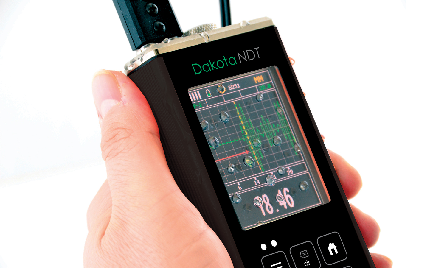
- Exceptional visibility in sunlight (AMOLED)
- colour VGA display (320x240 pixels)
- Sizing Toolkits: DAC, AWS, TCG, DGS
- Pulse Repetition Frequency: 8 to 2000Hz, adjustable
- Detection: Z-Cross, Flank & Peak
- Automatic: probe zero, probe recognition, and temperature compensation
- Measurement: Variety of modes to address a number of applications
- Large data storage with multiple formats: Alpha numeric grid and sequential with auto identifier
- Download to DakMaster™ data management software
-
- Key Features
-
Key Features
Dakota FX71-DL Flaw Detector (DFX-7)
Support & Resources
Application Notes
Explore how to get the most out of your Dakota FX71 Gauge.
Transducer Options
A wide range of Flaw Detector Transducers are available.
DakMaster™
From inspection to professional reports at the click of a button.
Detection Methods
Zero Crossing:
The gate detects the flank of the pulse, but the measurement is taken at the next crossing of the x axis. This is the most common type of detect in ultrasonic measurement.
Flank:
The gate is triggered by the flank (or side) of the pulse on the graph and the measurement taken at this exact point.
Peak:
The gate is triggered by the intersection with the A-scan pulse and the detection is taken from the next peak in the signal (when it stops rising and starts falling).
TRIG:
TRIG enabling location of flaws in both surface distance and depth. Trigonometric display of beam path, depth, surface distance, and curved surface correction. Used with angle beam transducers.
DAC:
Distance amplitude correction for the creation of DAC curves which are used to inform the operator of the size of any given flaw at any depth.
AWS:
The American Weld Standard function provides automatic defect sizing in accordance with AWS D1.1 structural welding code.
TCG:
Time corrected gain increases gain as distance increases, in order to achieve an over all level of sensitivity for the same flaw/reflector at different distances.
Firmware Upgrades
Regularly checking and updating your firmware is crucial for maintaining performance, and ensuring compatibility with new features.
Make sure your Dakota Flaw Detector is running the latest firmware, select your gauge below.
Dakota Ultrasonics DFX-7
Dakota NDT FX71-DL
-
- Technical Information
-
Technical SpecificationDakota FX71-DL Flaw Detector (DFX-7)
Part Number Description Certificate Z-221-0005 Dakota FX71-DL Flaw Detector (DFX-7+) 
Operating Temperature -10 to 60ºC (14 to 140ºF) Power Supply 3 x AA batteries and via USB Battery Life2 Alkaline (12hrs), Nicad (5hrs), and NI-MH (12hrs) Gauge Weight 397g (14oz) - including batteries Gauge Dimensions 63.5 x 165 x 31.5mm (2.5 x 6.5 x 1.24”) Packing List Unit, Couplant, Manual, Plastic Carrying Case, Certificate of Calibration and AA Batteries. PC Software and Data Transfer Cable ● Certificate of Calibration supplied as standard
-
- Standards
-
StandardsDakota FX71-DL Flaw Detector (DFX-7)
Thickness Gauge: Factory calibration traceable to NIST & MIL-STD-45662A.
Flaw Detector: EN12668-1 compliant.
-
- Downloads
-
Downloads
-
Dakota FX70-DL Flaw Detector - Flaw Instruction Manual
-
Dakota FX70-DL Flaw Detector - Thickness Instruction Manual
-
Dakota FX71-DL Flaw Detector Datasheet
-
Dakota FX71-DL CE Certificate - FCC
-
Dakota FX71-DL CE Certificate - EN 61326
-
Dakota FX71-DL CE Certificate - Compliance
- Part Numbers
-
Part NumbersDakota FX71-DL Flaw Detector (DFX-7)
-
 Dakota FX71-DL Flaw Detector (DFX-7+)
- Part Number : Z-221-0005
-
Dakota FX71-DL Flaw Detector (DFX-7)
The hand-held Dakota FX71-DL Flaw Detector range combines state-of-the-art flaw detection with advanced material thickness capabilities.
Versatile
Two gauges in one
The Dakota FX71-DL Flaw Detector series has two functions, a thickness gauge and a flaw detector. When the Dakota FX71-DL Flaw Detector is set to thickness gauge it has the ability to measure coatings and material thickness simultaneously. When set to flaw detector the gauge has the ability to detect the size and position of flaws and to differentiate between flaw types in various materials and welded joints.
Intelligent
User definable limits for pass/fail indication
Set hi/lo limits for pass/fail indication with audible warnings and built-in differential mode for quality control inspections.
Powerful
Store each measurement for further analysis
Up to 4GB of readings can be saved into the gauge memory as each measurement is taken, which can be downloaded later into an inspection application or into DakMaster™ Software for further analysis and reporting.
Customisable
Customisable tool kits and reading display
The Dakota FX71-DL Ultrasonic Flaw Detector has a choice of display modes allowing the user to select the most appropriate for their needs; from A & B-Scan displays to flaw detection modes such as TRIG, DAC, TCG, Flank and Peak.
Summary
Dakota FX71-DL Flaw Detector (DFX-7)
Whether you are on-site or in the laboratory this gauge is the tool you need for all your flaw detecting needs.
The time corrected gain (TCG) feature automatically compensates for sound attenuation through a material, further increasing the performance of the gauge.
The Dakota FX71-DL Ultrasonic Flaw Detector stores up to 4GB worth of readings with A/B-scan images in alpha numeric batches with full data logging and firmware updates via USB data output to DakMaster™ data management software.
Features:
- Exceptional visibility in sunlight (AMOLED)
- colour VGA display (320x240 pixels)
- Sizing Toolkits: DAC, AWS, TCG, DGS
- Pulse Repetition Frequency: 8 to 2000Hz, adjustable
- Detection: Z-Cross, Flank & Peak
- Automatic: probe zero, probe recognition, and temperature compensation
- Measurement: Variety of modes to address a number of applications
- Large data storage with multiple formats: Alpha numeric grid and sequential with auto identifier
- Download to DakMaster™ data management software
Downloads-
Dakota FX70-DL Flaw Detector - Flaw Instruction Manual
-
Dakota FX70-DL Flaw Detector - Thickness Instruction Manual
-
Dakota FX71-DL Flaw Detector Datasheet
-
Dakota FX71-DL CE Certificate - FCC
-
Dakota FX71-DL CE Certificate - EN 61326
-
Dakota FX71-DL CE Certificate - Compliance
Key Features
Dakota FX71-DL Flaw Detector (DFX-7)
Support & Resources
Application Notes
Explore how to get the most out of your Dakota FX71 Gauge.
Transducer Options
A wide range of Flaw Detector Transducers are available.
DakMaster™
From inspection to professional reports at the click of a button.
Detection Methods
Zero Crossing:
The gate detects the flank of the pulse, but the measurement is taken at the next crossing of the x axis. This is the most common type of detect in ultrasonic measurement.
Flank:
The gate is triggered by the flank (or side) of the pulse on the graph and the measurement taken at this exact point.
Peak:
The gate is triggered by the intersection with the A-scan pulse and the detection is taken from the next peak in the signal (when it stops rising and starts falling).
TRIG:
TRIG enabling location of flaws in both surface distance and depth. Trigonometric display of beam path, depth, surface distance, and curved surface correction. Used with angle beam transducers.
DAC:
Distance amplitude correction for the creation of DAC curves which are used to inform the operator of the size of any given flaw at any depth.
AWS:
The American Weld Standard function provides automatic defect sizing in accordance with AWS D1.1 structural welding code.
TCG:
Time corrected gain increases gain as distance increases, in order to achieve an over all level of sensitivity for the same flaw/reflector at different distances.
Firmware Upgrades
Regularly checking and updating your firmware is crucial for maintaining performance, and ensuring compatibility with new features.
Make sure your Dakota Flaw Detector is running the latest firmware, select your gauge below.
Dakota Ultrasonics DFX-7
Dakota NDT FX71-DL
Technical SpecificationDakota FX71-DL Flaw Detector (DFX-7)Part Number Description Certificate Z-221-0005 Dakota FX71-DL Flaw Detector (DFX-7+) Operating Temperature -10 to 60ºC (14 to 140ºF) Power Supply 3 x AA batteries and via USB Battery Life2 Alkaline (12hrs), Nicad (5hrs), and NI-MH (12hrs) Gauge Weight 397g (14oz) - including batteries Gauge Dimensions 63.5 x 165 x 31.5mm (2.5 x 6.5 x 1.24”) Packing List Unit, Couplant, Manual, Plastic Carrying Case, Certificate of Calibration and AA Batteries. PC Software and Data Transfer Cable ● Certificate of Calibration supplied as standardStandardsDakota FX71-DL Flaw Detector (DFX-7)Thickness Gauge: Factory calibration traceable to NIST & MIL-STD-45662A.
Flaw Detector: EN12668-1 compliant.
-
-