Considerations for Ultrasonic Transducer Selection
Application Overview:
A thickness gauge will specify a measurement range however, it is actually the transducer and the material to be inspected that ultimately determines the true measurement ranges achievable. Selecting the optimal performing transducer is critical. This document will explain the principles of transducer operation and offer support when selecting the optimal transducer.
A transducer converts an electrical signal into a sound vibration. The sound travels through the target material, dissipating and losing power as it travels through. Once the sound hits a backwall, or an indication from a material change, such as a crack inside the material, a proportion of the sound is reflected back towards the transducer.
The reflected sound vibration is then converted to an electrical signal by the transducer and then in turn converted by the thickness gauge receiver circuit into a reading. The time taken for the pulse to travel to and from the reflection indicates the distance/thickness. The sound and signal levels indicate the size of the reflection.
Transducer Frequency / Resolution:
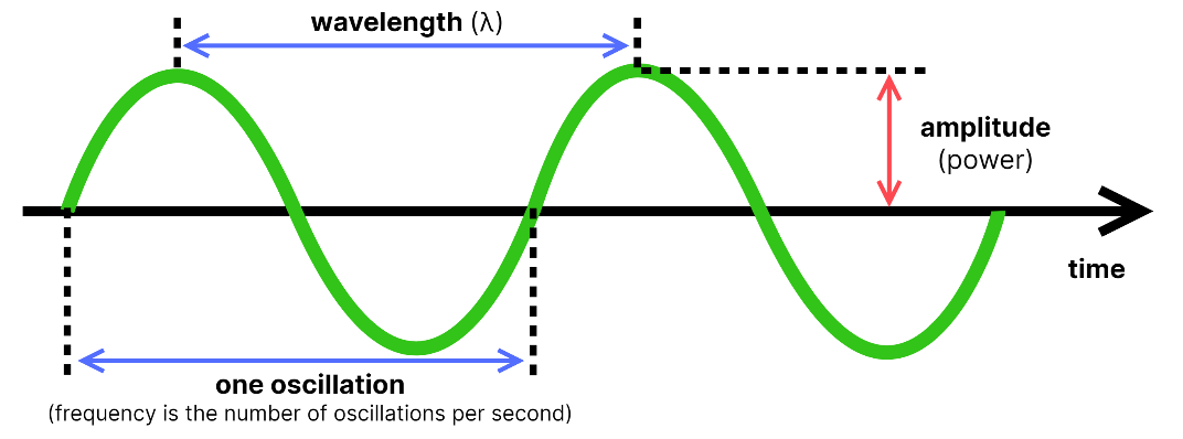
Transducers are listed by frequency and size, specifically their diameter. Each crystal has a set frequency operating band for maximum performance. As a general rule, the minimum detectable defect size is half the wavelength. From this we can deduce that a higher frequency transducer has increased resolving power and this enables improved detection of smaller indications.
With High Frequency and improved resolution there is a concern. At high frequency, signal is attenuated by the material reducing the signal strength significantly in certain materials.
A lower frequency pulse will generally pass through a material easier and be more able to penetrate further and measure deeper. This often comes as loss of signal resolution and defect indication detail.
Diameter Consideration:
The Diameter of a transducer has 2 impacts on measurements:
1) Physical Dimensions of the Transducer:
Is the transducer able to have good contact with the surface? Can the inspector hold and manipulate it?
2) Transducer Power:
The larger the transducer crystal the more power and less the beam from the transducer spreads. The smaller the diameter, the more the beam spreads and the less energy is passed into the material. Small diameters are better for thinner material and larger diameters are better for thicker material.
Near Field:
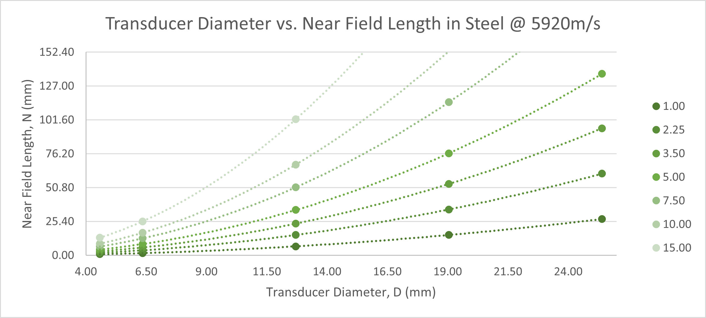
As discussed earlier a transducer has a frequency and a diameter. Using this information a calculation for the near field can be made. The Near Field must be considered when determining potential measurement ranges and limitations.
Inside the Near Field of a transducer we say the transducer is ‘unreliable’ and the signal response is not normally used. After the first near field the signal is uniform and useable. For flaw detection we say the range of the field is equivalent to 1-5 near field lengths. For thickness measurement this length can be increased.
| Transducer Diameter, D (mm) | Near Field Length @ x MHz, N (mm) | ||||||
1.00 | 2.25 | 3.50 | 5.00 | 7.50 | 10.00 | 15.00 | |
4.57 | 0.88 | 1.99 | 3.09 | 4.41 | 6.62 | 8.83 | 13.24 |
6.35 | 1.70 | 3.83 | 5.96 | 8.51 | 12.77 | 17.03 | 25.54 |
12.70 | 6.81 | 15.33 | 23.84 | 34.06 | 51.08 | 68.11 | 102.17 |
19.05 | 15.33 | 34.48 | 53.64 | 76.63 | 114.94 | 153.25 | 229.88 |
25.40 | 27.24 | 61.30 | 95.36 | 136.22 | 204.34 | 272.45 | 408.67 |
| Transducer Diameter, D (in) | Near Field Length @ x MHz, N (in) | ||||||
1.00 | 2.25 | 3.50 | 5.00 | 7.50 | 10.00 | 15.00 | |
0.180 | 0.035 | 0.078 | 0.122 | 0.174 | 0.261 | 0.348 | 0.521 |
0.250 | 0.067 | 0.151 | 0.235 | 0.335 | 0.503 | 0.670 | 1.006 |
0.500 | 0.268 | 0.603 | 0.939 | 1.341 | 2.011 | 2.682 | 4.022 |
0.750 | 0.603 | 1.358 | 2.112 | 3.017 | 4.525 | 6.034 | 9.050 |
1.000 | 1.073 | 2.413 | 3.754 | 5.363 | 8.045 | 10.726 | 16.090 |
Example tables for Near Field Length in Steel at varying transducer frequencies and diameters
Resolving Near Field Issues:
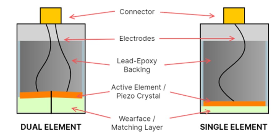
Twin Crystal Transducers or Dual Element Transducers:
A single crystal probe can have near surface limitations. Twin crystal transducer resolves these limitations. A twin crystal transducer is used for most corrosion and general thickness applications.
Twin Crystal, sometimes called Dual Crystal, sends a signal on one transducer and receives on another, this reduces the near field noises and improves signal recovery. A twin crystal has 2 crystals that are mounted at slight angles towards each other. This enables better near surface focusing. These twin crystals enable a much better near surface measuring ability. This is why most corrosion measurement is performed by twin crystals.
Twin Crystal transducers do not have long range measuring ability due to the distance limitation from the focus of the angled crystal placement or “V-Path”.
Precision Transducers:
Adding a perspex delay to a single crystal transducer of high frequency and small diameter will ensure the erratic non-linear near field is contained inside the wedge. This enables very thin part measurement.
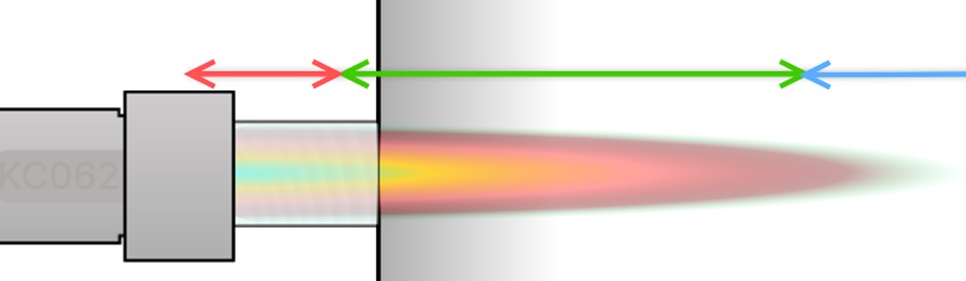
Table of Dakota CX Corrosion Thickness & Dakota PCX Precision Thickness Transducers and Application Considerations:
| Identifying Part Numbers | Dakota Part Numbers | Transducer Selection Guide / Application Considerations | Transducer Details | Compatibility | PE Measurement Range | EE / Through Coat Measurement Range | EE Coating Depth Limit | Max Temp Constant Placement | Max Temp Intermittent Placement |
| TXC1M00EP-2 | T-1049-0000 | Specifically designed for measurement of composite, plastic and other challenging materials such as old Iron, boats, plastic storage tanks, GFRP, stainless steel. Please Note - Typically 5-35mm/0.196-1.37" - consider using a single contact solution in certain circumstances. | 1Mhz, 1/2” Dia, Side Entry Potted | CX4/6/8 | '5.00-50mm / 0.196-1.96" | N/A | N/A | 220F = 104C | 260F = 126C |
| TXC5M00CP-4 | T-1029-2000 | Standard general purpose transducer for metal thickness measurement. Corrosion wall loss, plates, pipelines, cast parts. Please Note - Most commonly selected general thickness transducer. | 5Mhz, 1/4” Dia, Side Entry Potted | CX2/4/6/8 | '2.00-152mm / 0.078-6.00" | N/A | N/A | 220F = 104C | 260F = 126C |
| TXC5M00CP-10 | T-1029-2700 | Specifically designed as a general purpose and EE transducer. For measurement undercoating and also for general metal thickness measurement. Corrosion wall loss, plates, smaller pipelines above 40mm/1.96" Dia & 5mm/0.196" thickness, measurement under thinly coated surfaces. | 5Mhz, 1/4”Dia, Side Entry Potted – High Damped (HD) | CX4/6/8 | '2.00-152mm / 0.078-6.00" | '2.54-25.4mm / 0.100 - 1.00" | '1.1mm / 0.040" | 220F = 104C | 260F = 126C |
| TXC5M00EP-10 | T-1049-2700 | Specifically designed as a general purpose and EE transducer for larger parts. For measurement undercoating or rough, poor surface conditions. Can be used general metal thickness measurement PE/EE. Large parts, corrosion wall loss, plates, large Diameter Pipelines above 152mm/6.0" & 7.5mm/0.30" thickness, Riser Inspections. | 5Mhz, 1/2” Dia, Side Entry Potted – High Damped (HD) | CX4/6/8 | '2.54-500mm / 0.100-20.0" | '7.50-25-4mm / 0.100-1.00 | '1.9mm / 0.075" | 220F = 104C | 260F = 126C |
| TXC7M50BP-3 | T-1019-3000 | Specifically designed as a general purpose transducer for thinner metal thickness measurement that need a small diameter transducer contact face. Suitable for smaller diameter tubes and pipes such as, underground utility pipelines above 25mm/1.0" Diameter & 2mm/ 0.078" thickness. | 7.5Mhz, 3/16” Dia, Side Entry Potted | CX4/6/8 | '1.016-50mm / 0.040-1.968" | N/A | N/A | 220F = 104C | 260F = 126C |
| TXC7M50CP-4 | T-1029-3300 | Precision measurement accuracy. Specifically designed for thinner metal thickness measurement where a high degree of accuracy is required. Thinnest reading ability of all CX transducers. Can be used as a general purpose transducer. | 7.5Mhz, ¼” Dia,Side Entry – Extra Resolution | CX4/6/8 | '0.75-150mm / 0.030-5.906" | N/A | N/A | 220F = 104C | 260F = 126C |
| TXC5M00CP-8 | T-0429-2000 | Specifically designed as a general purpose transducer for use at high temperatures. 650F / 343C, boilers, refinery structures and pipelines above 40mm/1.96" Dia & 5mm/0.196" thickness. | 5Mhz, ¼” Dia, Side Entry Potted – High Temperature (HT) | CX4/6/8 | '2.00-152mm / 0.078-6.00" | N/A | N/A | 500F = 260C | 635F = 335C |
| Identifying Part Numbers | Dakota Part Numbers | Transducer Selection Guide / Application Considerations | Transducer Details | Compatibility | IE Measurement Range | IEE Measurement Range | EE Coating Depth Limit | Max Temp Constant Placement | Max Temp Intermittent Placement |
| TXC15M0CM | T-4029-5507 | Specifically designed for thin metallic and plastic parts precision measurement, Perspex and Graphite delay tips options possible ** - Not suitable for cone/pencil delay tips. Metallic machined parts, composite parts, plastic containers, thin part corrosion, automotive, aircraft and very small diameter thin pipes and hoses. Less than 25mm/1.0" Diameter, 2mm/0.078" thickness. | 15Mhz, ¼” Dia, Delay type – Side Entry - Supplied with Cable | PCX8-DL | See Delay | See Delay | N/A | 110F = 52C | 110F = 52C |
| F-000-7102 | F-000-7102 | ** 15MHz 1/4" With 9mm(3/8") Removable Delay Line. | Removable Delay | PCX8-DL | '1.65-20.0mm / 0.065-0.787" | '0.15-10.0mm / 0.0059-0.394" | N/A | 110F = 52C | 110F = 52C |
| F-0007103 | F-0007103 | ** 15MHz 1/4" With 12mm(1/2") Removable Delay Line. | Removable Delay | PCX8-DL | '1.65-25.0mm / 0.065-0.984" | '0.15-10.0mm / 0.0059-0.394" | N/A | 110F = 52C | 110F = 52C |
| X-633-0000 | X-633-0000 | ** 15MHz 1/4" With 9mm(3/8") Graphite Removable Delay Line. | Removable Delay | PCX8-DL | '0.15-5.0mm / 0.0059-0.196" | 'N/A | 'N/A | 110F = 52C | 110F = 52C |
For more details on how the Dakota PCX Precision Thickness Transducers can give an advantage to your inspection process.