Bolt Tension Glue-On Pin Probes
Introduction:

Measuring bolt tension using standard ultrasonic transducers can be challenging on fasteners with complex geometries or small dimensions. Probe placement errors, difficulties coupling on uneven surfaces (like key-slots or raised markings), and inconsistencies on very small bolts can lead to inaccurate results. DakotaNDT has developed the Bolt Tension Pin Probe system to address these specific challenges.
Unlike typical integrated transducers (housing the piezoceramic crystal, electronics, damping, and wearface), the Pin Probe utilizes a two-part approach:
1. Consumable Stick-on Piezoceramic Crystals: Small, thin crystals adhered directly to the fastener.
2. Separate Pin-Contact Probe: Connects to the gauge and contacts the crystal to energize it.
This design enhances flexibility for difficult bolt tension measurements:
Obstructed Faces: Crystals can be placed inside deep key-slots or recesses, bypassing the obstruction.
Small Fasteners: Adhering the crystal ensures identical probe placement for initial (loose) and final (tightened) measurements, eliminating a significant source of error.
The Bolt Tension Pin Probe enables more accurate measurements on a wider range of bolts. However, the absence of integrated damping materials (found in standard transducers) means Pin Probe signals may exhibit more ringing and a potentially higher noise floor, requiring careful gauge setup.
Ideal Application Scenarios
While standard transducers are suitable for many applications, the Pin Probe excels in specific situations:
1. Fasteners with Obstructed Faces (e.g., Keyhole Bolts)
- Challenge: Keyholes, deep Allen hex recesses, or similar indentations prevent the large, flat face of standard (especially magnetic) transducers from achieving proper acoustic coupling. Direct contact is impossible, leading to unreliable measurements.
- Pin Probe Solution: The small, thin piezoceramic crystal is adhered directly to the flat base within the recess. The pin probe then only needs to contact the top of this crystal, effectively bypassing the complex surface geometry and allowing ultrasonic pulse transmission.
2. Bolts with Raised Surface Features (e.g., Embossed Grade Marks)
- Challenge: Raised markings (grade indicators, logos) can cause standard transducers to rest unevenly (“top-rocking”), creating air gaps that disrupt the ultrasonic signal. Stable contact may be impossible.
- Pin Probe Solution: The small crystal can be strategically placed and adhered to a flat area between the raised markings. This establishes a stable acoustic path unaffected by the surrounding features. The pin probe then contacts this precisely placed crystal.
3. Very Small Diameter Bolts and Screws

- Challenge: On small fasteners, the relatively large contact area of standard transducers makes repeatable placement difficult. Even slight shifts in position or angle between loose and tightened measurements can alter the ultrasonic path length, causing significant tension/elongation errors.
- Pin Probe Solution: The crystal is adhered to the bolt head once. This guarantees the exact same position and coupling for both measurements, eliminating placement error as a variable. After tightening, the operator simply touches the pin probe to the pre-placed crystal. This significantly improves accuracy and repeatability on small fasteners.
Operating Procedure
Using the Pin Probe system involves adhering a crystal and then using the pin probe for measurements:
1. Surface Preparation: Clean the target area on the fastener head thoroughly (remove dirt, grease, rust, scale). The surface must be clean, dry, and preferably flat for good adhesion and coupling. Use appropriate solvents if needed.
2. Adhesive Application: Apply a minimal amount of a suitable cyanoacrylate adhesive (DakotaNDT recommends Loctite 425) to the prepared surface. Excess adhesive can dampen the signal or increase cure time.
3. Crystal Placement: Carefully place the crystal onto the adhesive. Ensure it sits flat. Apply gentle, even pressure briefly to spread the adhesive thinly and ensure good contact.
Caution: Piezoceramic crystals are very brittle. Place them only on flat surfaces. Avoid curved or uneven areas. Bending or stress during placement/curing can fracture the crystal permanently. Broken crystals are unusable.
4. Adhesive Curing: Allow the adhesive to fully cure per the manufacturer’s instructions. Cure time depends on adhesive, temperature, and humidity.
5. Gauge Setup: Power on the Dakota NDT bolt tension gauge. Navigate to the appropriate setup tab (AUTO-SET) and input the fastener’s approximate nominal length to aid initial detection.
6. Connect Pin Probe: Plug the pin probe cable into the gauge’s transducer port.
7. Establish Contact:
- Dual Pin Probe (Signal/Ground): Gently press the probe so the centre pin contacts the crystal’s top surface and the outer ground contact touches the conductive metal surface of the bolt head or fixture. Proper grounding can reduce noise.
- Single Pin Probe: Press the pin tip gently onto the crystal’s top surface. Grounding may occur through the operator or test setup.
8. Acquire Measurement: With stable contact:
- Verify a stable ultrasonic waveform on the gauge. Adjust gain/threshold if needed.
- Use the gauge’s measurement function (‘MEASURE’/’AUTO-SET’) to capture the reading (time, elongation, load, etc.).
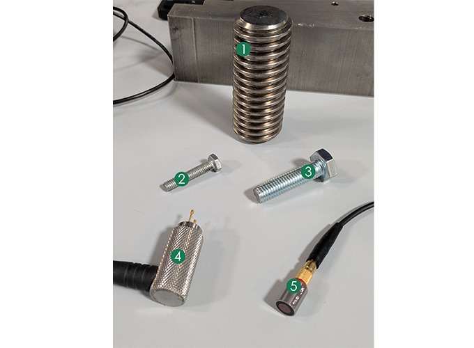
Equipment Used:
1. 3” Calibration Bar: X-000-0011
2. M7 x 34 Small Bolt
3. M10 x 45 Small Bolt
4. Spring Loaded 2-Pin Fixture 1/4” Spacing: N-704-0094
5. 10MHz Magnetic Transducer: T-700-4405
1. Calibration Bar
- On ideal flat surfaces, both types yield clear signals.
- The Pin Probe signal may show slightly more ringing (slower echo decay) due to the lack of integrated damping compared to standard transducers. Both are effective for basic calibration.

2. Small Screw (e.g., M7 x 34 Bolt)
- Signal Quality: The Pin Probe waveform again shows more ringing. Gauge detection gates may need careful adjustment.
- Placement Consistency: This is the Pin Probe’s key advantage here. The waveform shown is achieved by simply contacting the pre-glued crystal. Achieving identical placement with a standard magnetic transducer after tightening is difficult and prone to error on such a small head. The Pin Probe eliminates this variable.

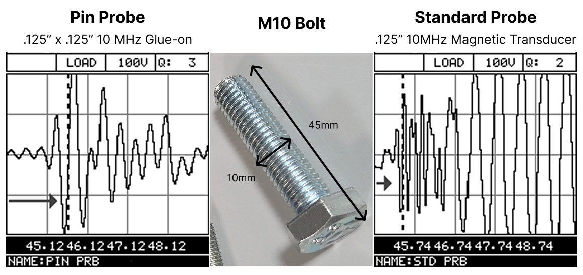
3. Small Bolt (e.g., M10 x 45 Bolt) with Surface Obstructions
This scenario highlights the Pin Probe’s strengths on challenging geometries.
- Pin Probe Signal: Clear, well-defined waveform with distinct echoes. Achieved by placing the small crystal on a flat area between raised grade markings, ensuring good coupling.
- Standard Probe Signal: Significantly degraded, noisy waveform. The larger standard probe is slightly tilted and off-axis on the raised markings, preventing flat contact and hindering signal transmission.
- Comparison Conclusion: The Pin Probe excels where small size and surface obstructions exist. It provided a clear signal where the standard transducer struggled due to the geometry preventing flat contact. The Pin Probe enables measurements that might otherwise be impossible and ensures high repeatability via the fixed crystal.
Key Considerations and Limitations
Users should be aware of these factors:
- Signal Characteristics: Expect more signal ringing and potentially a higher noise floor compared to standard damped transducers. Careful gauge setup (gain, threshold, gates) is often necessary.
- Consumable Crystals: Crystals are fragile, consumable items, typically single-use. Factor replacement cost and logistics into planning. Handle with care.
- Adhesive Process: Requires surface preparation, adhesive application, and curing time, adding steps compared to direct-contact transducers. Correct adhesive choice and application are crucial.
- Surface Requirement: Needs a small, flat area on the fastener for mounting the crystal without stress. Not suitable if no such flat area exists.
Conclusion
The DakotaNDT Bolt Tension Pin Probe is a valuable tool for ultrasonic bolt tensioning in specific challenging applications. By using a separate, consumable crystal adhered to the fastener, it overcomes limitations faced by standard transducers on bolts with obstructed faces, raised features, or very small diameters where placement consistency is critical.
While considerations regarding signal characteristics, consumable nature, and the adhesive process exist, the Pin Probe enables accurate, repeatable measurements on a wider range of fasteners, improving quality control where conventional methods may fail or produce unreliable results.
Dakota equipment used in this application:
For more details on how the Dakota BT1-DL Bolt Tension Monitor can give an advantage to your inspection process.