

Dakota CMX Corrosion Thickness Gauges
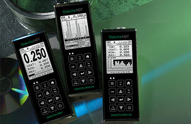
Top of the range and easy to use, the Dakota CMX Corrosion Thickness Gauges provide inspectors with all the features necessary to measure the material and coating thickness at the same time.
- Zusammenfassung
-
Zusammenfassung
-
Intelligent
User definable limits for pass/fail indication
Set limits for pass/fail indication on individual reading or for each batch with audible & visual warnings.
Powerful
Store each measurement for further analysis
Up to 4GB of readings can be saved into the gauge memory as each measurement is taken, which can be downloaded later into an inspection application or into DakMaster™ Software for further analysis and reporting.
Versatile
Able to measure coating and material thickness
The Dakota CMX Ultrasonic Corrosion Thickness Gauges have the ability to measure coatings and material thickness simultaneously while maintaining the ability to locate pits, flaws and defects in the material.
Customisable
Choose & customise the reading display
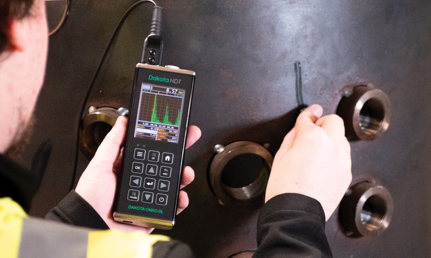
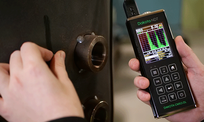
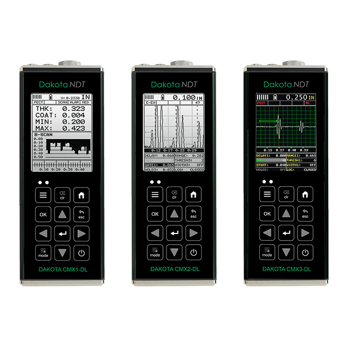
The Dakota CMX Corrosion Thickness Gauge range has a choice of display modes allowing the user to select the most appropriate for their needs; Readings, B-Scan, B-Scan combined with readings, Scan bar & the A-Scan on the Dakota CMX2-DL Corrosion Thickness Gauge and Dakota CMX3-DL Corrosion Thickness Gauge.
The Dakota CMX ultrasonic corrosion thickness gauge is available in four models - from an entry level Dakota CMX1-DL Ultrasonic Corrosion Thickness Gauge to the top of the range Dakota CMX3-DL Ultrasonic Corrosion Thickness Gauge.
- Range of display & measurement options: Pulse-Echo, Echo-Echo, Pulse-Echo Temp, Comp Mode (PETP), Coating Only Mode (CT), Pulse-Echo Coating Mode (PECT)
- Manual or automatic gain control (AGC) with adjustable 110dB range
- Gate control
- Threshold adjustment
- 64 User defined setups
- Multiple language display
- Multiple calibration and material selection options
- High speed scan mode: 250 readings per second (Dakota CMX1-DL Ultrasonic Corrosion Thickness Gauge), 50 readings per second (Dakota CMX2-DL Ultrasonic Corrosion Thickness Gauge and Dakota CMX3-DL Ultrasonic Corrosion Thickness Gauge)
- A-Scan portrait & landscape views (Dakota CMX3-DL Ultrasonic Corrosion Thickness Gauge only)
- Differential and minimal thickness alarm modes
- Data output and storage: 4GB internal memory
- Download to DakMaster™ data management software
-
- Hauptmerkmale
-
Hauptmerkmale
Dakota CMX Corrosion Thickness Gauges
Support & Resources
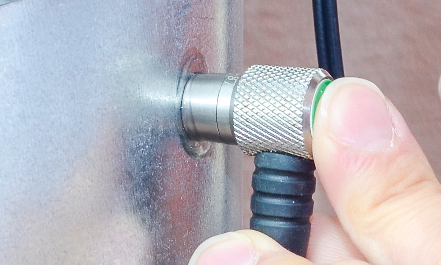
Transducer Options
A wide range of Corrosion Thickness Transducers available.
DakMaster™
From inspection to professional reports at the click of a button.
Application Notes
Explore how to get the most out of your Dakota CMX Gauge.
Dakota CMX Features Explained
Repeatability / Stability Indicator
Consisting of 6 vertical bars, when all the bars are fully illuminated and the last digit on the digital thickness value is stable, the gauge is reliably measuring the material thickness.
High Speed Scan with Minimum Thickness Display
By significantly increasing the measurement refresh rate this mode allows the user to make scanned passes over the test material. The smallest thickness value is held in memory and displayed when scanning is complete. This feature can also be used in conjunction with the minimum & maximum limit alarm feature (model dependant).
Differential Mode
Once a user defined nominal thickness value has been set, the gauge will display the +/- thickness difference from the nominal value entered.
Limit Alarm Mode
The user can define minimum and maximum thickness limits. If the measurement falls outside the upper or lower limit a red LED will light and the beeper sounds. A green LED will light to indicate an acceptable thickness.
V-Path Correction
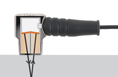
Dual element transducers consist of a probe with two crystals (one to transmit and one to receive the sound pulse). The crystals are separated by an acoustic barrier - generating a 'V-shaped' sound path as the sound travels from one element to the other. This path is slightly longer than the direct path therefore V-path correction is used to calculate the correct thickness
Measurement Modes Explained
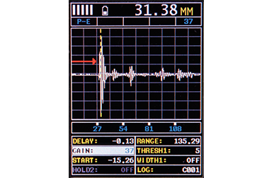
Pulse - Echo Mode (PE):
The normal display mode, measures the total thickness from the base of the transducer probe to the material density boundary (typically the back wall). Ideal for pit and flaw detection.
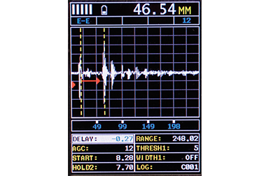
Echo - Echo Mode (EE):
Also known as the ThruPaint™ Mode, EE ignores the coating thickness, displaying the material thickness from the top surface of the material to the material density boundary.
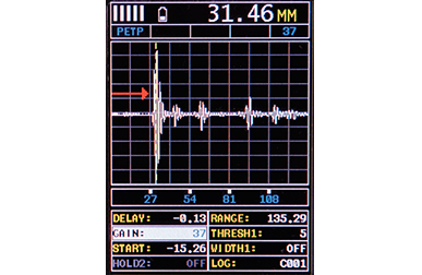
Pulse - Echo Temp Comp Mode (PETP):
Similar to the PE mode, PETP takes into account and compensates for the variations in measurement caused by temperature variations.
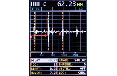
Echo - Echo Verify Mode (EEV):
The echo-echo verify mode measures by comparing the values between 3 reflections and is commonly used to eliminate errors from surface coatings and to make measurements in multiple layered materials.
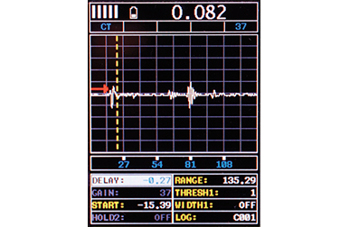
Coating Only Mode (CT):
Displays the thickness of the coating applied to the material.
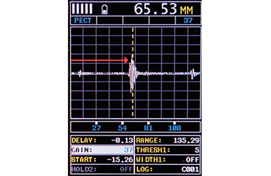
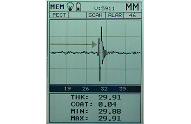
Pulse - Echo Coating Mode (PECT):
Displays both the material thickness (PE) and the coating thickness (CT) at the same time.
Basic Flaw Mode (FLAW MODE):
Basic prove-up flaw detection using single element angle beam transducers is available on the CMX2-DL and CMX3-DL corrosion thickness gauges.
Display Modes Explained
Material Thickness Digits Display:
The standard display on all models, this displays the numerical thickness value in either millimetres (MM)or inches (IN).
Scan Bar Display:
A linear graphic display which allows users to graphically monitor changes in thickness readings. As the scale range can be adjusted by the user, this display is ideal for observing tiny variations in material thicknesses.
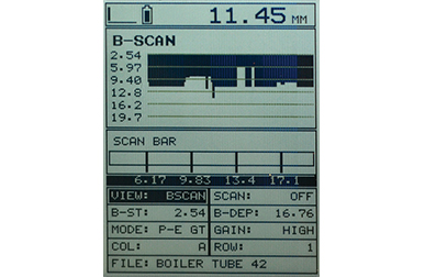
B-Scan Display:
A time based cross sectional 2D block view of the thickness provides a graphical view of the material thickness - ideal for relative depth analysis.
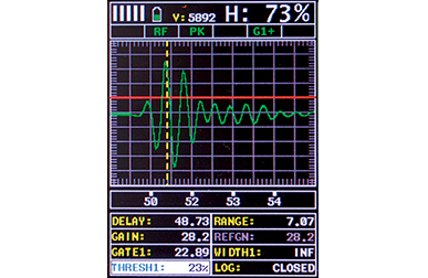
A-Scan Display; Full Wave (RF):*
The A-Scan display shows the sine wave created by the reflected sound, or oscillation, from the material being measured. In RF mode the full wave form is displayed.
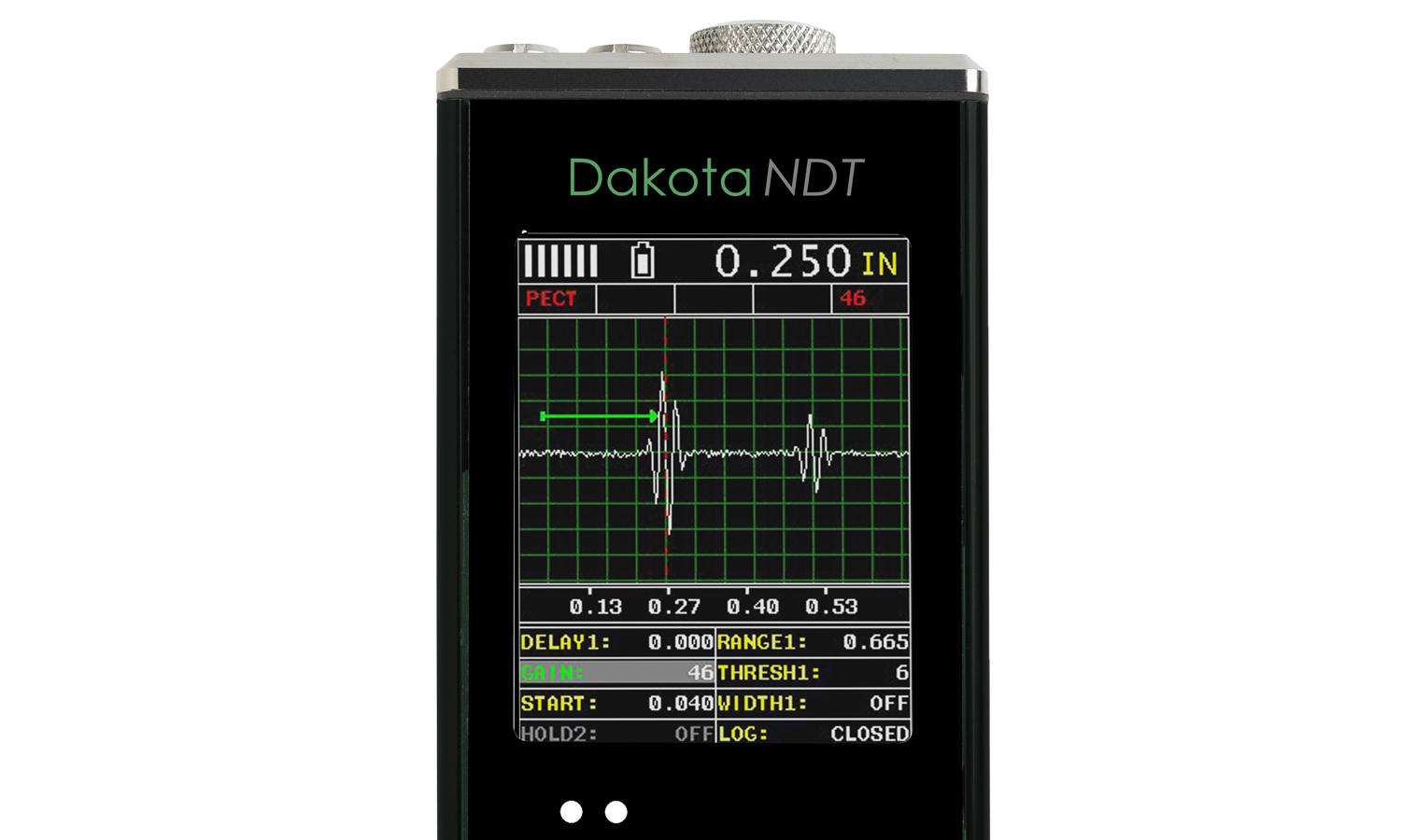
A-Scan Display; Rectified (+ or -):*
Users can select to view either the positive or the negative cycle of the full waveform (RF). This rectified (RECT) display shows the amplitude of the echo versus the transit time.
* Available on CMX2-DL and CMX3-DL thickness gauge Models only
Firmware Upgrades
Regularly checking and updating your firmware is crucial for maintaining performance, and ensuring compatibility with new features.
Make sure your Dakota Corrosion Thickness Gauge is running the latest firmware, select your gauge below.
Dakota Ultrasonics CMX
Dakota NDT CMX
-
- Produkteigenschaften
-
ProdukteigenschaftenDakota CMX Corrosion Thickness Gauges
Model CMX1-DL CMX2-DL CMX3-DL Anzeigemodus Numerische Materialdickenanzeige B-Bild-Querschnittanzeige B-Bild mit numerischer Anzeige Beschichtungsdickenanzeige Scanleistenanzeige A-Bild-Anzeige + gerichtet, - gerichtet, vollständige Wellenform (RF)+ gerichtet, - gerichtet, vollständige Wellenform (RF) Ansicht im Hoch- und im QuerformatCMX Measurement Range PE: 0.63 - 1219.2mm
(0.025 - 48”)
PETP: 0.63 - 1219.2mm
(0.025 - 48”)
EE: 2.54 - 152.4mm
(0.100 - 6.0“)
EEV: 1.27 - 25.4mm
(0.050 - 1.0”)
CT: 0.01 - 2.54mm
(0.0005 - 0.100”)
PECT: 0.63 - 1219.2mm
(0.025 - 48”)
PECT: 0.01 - 2.54mm
(0.001 - 0.100")PE: 0.63 - 1219.2mm
(0.025 - 48”)
PETP: 0.63 - 1219.2mm
(0.025 - 48”)
EE: 2.54 - 152.4mm
(0.100 - 6.0“)
EEV: 1.27 - 25.4mm
(0.050 - 1.0”)
CT: 0.01 - 2.54mm
(0.0005 - 0.100”)
PECT: 0.63 - 1219.2mm
(0.025 - 48”)
PECT: 0.01 - 2.54mm
(0.001 - 0.100")PE: 0.63 - 1219.2mm
(0.025 - 48”)
PETP: 0.63 - 1219.2mm
(0.025 - 48”)
EE: 2.54 - 152.4mm
(0.100 - 6.0“)
EEV: 1.27 - 25.4mm
(0.050 - 1.0”)
CT: 0.01 - 2.54mm
(0.0005 - 0.100”)
PECT: 0.63 - 1219.2mm
(0.025 - 48”)
PECT: 0.01 - 2.54mm
(0.001 - 0.100")Measurement Rate Manuell 8 Messwerte pro Sekunde8 Messwerte pro Sekunde8 Messwerte pro SekundeScanmodus 250 Messwerte pro Sekunde50 Messwerte pro Sekunde50 Messwerte pro SekundeScanleistenanzeige 33 Hz33 Hz33 HzMessauflösung 0,01mm (0,001”)0,001 mm (0,0001”) wählbar0,001 mm (0,0001”) wählbarGeschwindigkeitskalibrierbereich 309,88 - 18,542m/s (0,0122 - 0,7300in/μs)309,88 - 18,542m/s (0,0122 - 0,7300in/μs)309,88 - 18,542m/s (0,0122 - 0,7300in/μs)Zusätzliche Funktionen Schnellscanmodus Differenzmodus Grenzwertalarmmodus B-Bild-Anzeigegeschwindigkeit 10 - 200 Messwerte pro Sekunde10 - 200 Messwerte pro Sekunde10 - 200 Messwerte pro SekundeMaterialfehlermodus Einfache Materialfehlererkennung mittels Einelement-WinkelstrahlmessköpfenEinfache Materialfehlererkennung mittels Einelement-WinkelstrahlmessköpfenKalibrierkonfigurationen 64 benutzerdefinierbare, zum und vom PC-Archiv übertragbare KonfigurationenBlende 3 voll einstellbare Blenden: Start, Stopp, Breite und Schwellenwert3 voll einstellbare Blenden: Start, Stopp, Breite und SchwellenwertGedämpft Einstellbare Dämpfung (50 - 1500 Ohm)Einstellbare Dämpfung (50 - 1500 Ohm)Impulsgebertyp Zwei Rechteckimpulsgeber
Bis zu 250Hz ImpulswiederholrateZwei Rechteckimpulsgeber
Bis zu 250Hz ImpulswiederholrateZwei Rechteckimpulsgeber
Bis zu 250Hz ImpulswiederholrateVerstärkung Manuelle oder automatische Verstärkungsregelung (AGC) mit 110-dB-Bereich (begrenzt)Automatische Signalverstärkung (AGC) bis zu 110dB (begrenzt), Linear zeitabhängige Verstärkung (TDG) mit einstellbarem AnstiegAutomatische Signalverstärkung (AGC) bis zu 110dB (begrenzt), Linear zeitabhängige Verstärkung (TDG) mit einstellbarem AnstiegTiming Temperaturkontrollierter Präzisions-Quarz-Oszillator (TCXO). Timing mit einem einzigen Signal von 100MHz mit ultra-energiesparendem 8-Bit-DigitizerTemperaturkontrollierter Präzisions-Quarz-Oszillator (TCXO). Timing mit einem einzigen Signal von 100MHz mit ultra-energiesparendem 8-Bit-DigitizerTemperaturkontrollierter Präzisions-Quarz-Oszillator (TCXO). Timing mit einem einzigen Signal von 100MHz mit ultra-energiesparendem 8-Bit-DigitizerSpeicher und Datenaufzeichnung • 4 GB interner Speicher
• Sequentiell und Rasteraufzeichnung
• Alphanumerische Loskennung
• OBSTRUCT verweist auf unzugängliche Stellen
• Bitmap Grafikerfassung und Signalbetrachtung• 4 GB interner Speicher
• Sequentiell und Rasteraufzeichnung
• Alphanumerische Loskennung
• OBSTRUCT verweist auf unzugängliche Stellen
• Bitmap Grafikerfassung und Signalbetrachtung• 4 GB interner Speicher
• Sequentiell und Rasteraufzeichnung
• Alphanumerische Loskennung
• OBSTRUCT verweist auf unzugängliche Stellen
• Bitmap Grafikerfassung und SignalbetrachtungKalibrieroptionen 1-Punkt 2-Punkt Materialauswahl Geschwindigkeit (Schallgeschwindigkeit) Messkopfsondentyp ZweielementDual Element, Single Element (1 - 20Mhz), ContactDual Element, Single Element (1 - 20Mhz), ContactMesskopffrequenzbereich 1 - 10MHz1 - 10MHz1 - 20MHzMesskopferkennung Automatisch und manuell - aus einer Liste wählbarAutomatisch und manuell - aus einer Liste wählbarAutomatisch und manuell - aus einer Liste wählbarV-Pfad- / Doppelpfad-Fehlerkorrektur automatischautomatischautomatischSondennullung Automatisch und manuell (über integrierte Sondenscheibe)Automatisch und manuell (über integrierte Sondenscheibe)Automatisch und manuell (über integrierte Sondenscheibe)Display 1/8” VGA (Grauskala)
62 x 45,7mm (2,4 x 1,8 Zoll) Anzeigebereich1/8” VGA (Grauskala)
62 x 45,7mm (2,4 x 1,8 Zoll) Anzeigebereich¼” VGA AMOLED-Farbdisplay
57,6 x 43,2 mm (2,27 x 1,78 Zoll) Anzeigebereich
QuerformatDisplayaktualisierungsrate 25Hz25Hz60HzEinheiten (wählbar) mm oder Zollmm oder Zollmm oder ZollLED-Hintergrundbeleuchtung Ein / Aus / AutomatischEin / Aus / AutomatischEinstellbare HelligkeitWiederholgenauigkeits-/Stabilitätsanzeige Batteriesparmodus AutomatischAutomatischAutomatischAnzeigemodus Numerische Materialdickenanzeige Z-171-0005 Z-172-0005 Z-187-0005 B-Bild-Querschnittanzeige Z-171-0005 Z-172-0005 Z-187-0005 B-Bild mit numerischer Anzeige Z-171-0005 Z-172-0005 Z-187-0005 Beschichtungsdickenanzeige Z-171-0005 Z-172-0005 Z-187-0005 Scanleistenanzeige Z-171-0005 Z-172-0005 Z-187-0005 A-Bild-Anzeige Z-171-0005 Z-172-0005 + gerichtet, - gerichtet, vollständige Wellenform (RF)Z-187-0005 + gerichtet, - gerichtet, vollständige Wellenform (RF) Ansicht im Hoch- und im QuerformatCMX Measurement Range Z-171-0005 PE: 0.63 - 1219.2mm
(0.025 - 48”)
PETP: 0.63 - 1219.2mm
(0.025 - 48”)
EE: 2.54 - 152.4mm
(0.100 - 6.0“)
EEV: 1.27 - 25.4mm
(0.050 - 1.0”)
CT: 0.01 - 2.54mm
(0.0005 - 0.100”)
PECT: 0.63 - 1219.2mm
(0.025 - 48”)
PECT: 0.01 - 2.54mm
(0.001 - 0.100")Z-172-0005 PE: 0.63 - 1219.2mm
(0.025 - 48”)
PETP: 0.63 - 1219.2mm
(0.025 - 48”)
EE: 2.54 - 152.4mm
(0.100 - 6.0“)
EEV: 1.27 - 25.4mm
(0.050 - 1.0”)
CT: 0.01 - 2.54mm
(0.0005 - 0.100”)
PECT: 0.63 - 1219.2mm
(0.025 - 48”)
PECT: 0.01 - 2.54mm
(0.001 - 0.100")Z-187-0005 PE: 0.63 - 1219.2mm
(0.025 - 48”)
PETP: 0.63 - 1219.2mm
(0.025 - 48”)
EE: 2.54 - 152.4mm
(0.100 - 6.0“)
EEV: 1.27 - 25.4mm
(0.050 - 1.0”)
CT: 0.01 - 2.54mm
(0.0005 - 0.100”)
PECT: 0.63 - 1219.2mm
(0.025 - 48”)
PECT: 0.01 - 2.54mm
(0.001 - 0.100")Measurement Rate Manuell Z-171-0005 8 Messwerte pro SekundeZ-172-0005 8 Messwerte pro SekundeZ-187-0005 8 Messwerte pro SekundeScanmodus Z-171-0005 250 Messwerte pro SekundeZ-172-0005 50 Messwerte pro SekundeZ-187-0005 50 Messwerte pro SekundeScanleistenanzeige Z-171-0005 33 HzZ-172-0005 33 HzZ-187-0005 33 HzMessauflösung Z-171-0005 0,01mm (0,001”)Z-172-0005 0,001 mm (0,0001”) wählbarZ-187-0005 0,001 mm (0,0001”) wählbarGeschwindigkeitskalibrierbereich Z-171-0005 309,88 - 18,542m/s (0,0122 - 0,7300in/μs)Z-172-0005 309,88 - 18,542m/s (0,0122 - 0,7300in/μs)Z-187-0005 309,88 - 18,542m/s (0,0122 - 0,7300in/μs)Zusätzliche Funktionen Schnellscanmodus Z-171-0005 Z-172-0005 Z-187-0005 Differenzmodus Z-171-0005 Z-172-0005 Z-187-0005 Grenzwertalarmmodus Z-171-0005 Z-172-0005 Z-187-0005 B-Bild-Anzeigegeschwindigkeit Z-171-0005 10 - 200 Messwerte pro SekundeZ-172-0005 10 - 200 Messwerte pro SekundeZ-187-0005 10 - 200 Messwerte pro SekundeMaterialfehlermodus Z-171-0005 Z-172-0005 Einfache Materialfehlererkennung mittels Einelement-WinkelstrahlmessköpfenZ-187-0005 Einfache Materialfehlererkennung mittels Einelement-WinkelstrahlmessköpfenKalibrierkonfigurationen Z-171-0005 Z-172-0005 Z-187-0005 64 benutzerdefinierbare, zum und vom PC-Archiv übertragbare KonfigurationenBlende Z-171-0005 Z-172-0005 3 voll einstellbare Blenden: Start, Stopp, Breite und SchwellenwertZ-187-0005 3 voll einstellbare Blenden: Start, Stopp, Breite und SchwellenwertGedämpft Z-171-0005 Z-172-0005 Einstellbare Dämpfung (50 - 1500 Ohm)Z-187-0005 Einstellbare Dämpfung (50 - 1500 Ohm)Impulsgebertyp Z-171-0005 Zwei Rechteckimpulsgeber
Bis zu 250Hz ImpulswiederholrateZ-172-0005 Zwei Rechteckimpulsgeber
Bis zu 250Hz ImpulswiederholrateZ-187-0005 Zwei Rechteckimpulsgeber
Bis zu 250Hz ImpulswiederholrateVerstärkung Z-171-0005 Manuelle oder automatische Verstärkungsregelung (AGC) mit 110-dB-Bereich (begrenzt)Z-172-0005 Automatische Signalverstärkung (AGC) bis zu 110dB (begrenzt), Linear zeitabhängige Verstärkung (TDG) mit einstellbarem AnstiegZ-187-0005 Automatische Signalverstärkung (AGC) bis zu 110dB (begrenzt), Linear zeitabhängige Verstärkung (TDG) mit einstellbarem AnstiegTiming Z-171-0005 Temperaturkontrollierter Präzisions-Quarz-Oszillator (TCXO). Timing mit einem einzigen Signal von 100MHz mit ultra-energiesparendem 8-Bit-DigitizerZ-172-0005 Temperaturkontrollierter Präzisions-Quarz-Oszillator (TCXO). Timing mit einem einzigen Signal von 100MHz mit ultra-energiesparendem 8-Bit-DigitizerZ-187-0005 Temperaturkontrollierter Präzisions-Quarz-Oszillator (TCXO). Timing mit einem einzigen Signal von 100MHz mit ultra-energiesparendem 8-Bit-DigitizerSpeicher und Datenaufzeichnung Z-171-0005 • 4 GB interner Speicher
• Sequentiell und Rasteraufzeichnung
• Alphanumerische Loskennung
• OBSTRUCT verweist auf unzugängliche Stellen
• Bitmap Grafikerfassung und SignalbetrachtungZ-172-0005 • 4 GB interner Speicher
• Sequentiell und Rasteraufzeichnung
• Alphanumerische Loskennung
• OBSTRUCT verweist auf unzugängliche Stellen
• Bitmap Grafikerfassung und SignalbetrachtungZ-187-0005 • 4 GB interner Speicher
• Sequentiell und Rasteraufzeichnung
• Alphanumerische Loskennung
• OBSTRUCT verweist auf unzugängliche Stellen
• Bitmap Grafikerfassung und SignalbetrachtungKalibrieroptionen 1-Punkt Z-171-0005 Z-172-0005 Z-187-0005 2-Punkt Z-171-0005 Z-172-0005 Z-187-0005 Materialauswahl Z-171-0005 Z-172-0005 Z-187-0005 Geschwindigkeit (Schallgeschwindigkeit) Z-171-0005 Z-172-0005 Z-187-0005 Messkopfsondentyp Z-171-0005 ZweielementZ-172-0005 Dual Element, Single Element (1 - 20Mhz), ContactZ-187-0005 Dual Element, Single Element (1 - 20Mhz), ContactMesskopffrequenzbereich Z-171-0005 1 - 10MHzZ-172-0005 1 - 10MHzZ-187-0005 1 - 20MHzMesskopferkennung Z-171-0005 Automatisch und manuell - aus einer Liste wählbarZ-172-0005 Automatisch und manuell - aus einer Liste wählbarZ-187-0005 Automatisch und manuell - aus einer Liste wählbarV-Pfad- / Doppelpfad-Fehlerkorrektur Z-171-0005 automatischZ-172-0005 automatischZ-187-0005 automatischSondennullung Z-171-0005 Automatisch und manuell (über integrierte Sondenscheibe)Z-172-0005 Automatisch und manuell (über integrierte Sondenscheibe)Z-187-0005 Automatisch und manuell (über integrierte Sondenscheibe)Display Z-171-0005 1/8” VGA (Grauskala)
62 x 45,7mm (2,4 x 1,8 Zoll) AnzeigebereichZ-172-0005 1/8” VGA (Grauskala)
62 x 45,7mm (2,4 x 1,8 Zoll) AnzeigebereichZ-187-0005 ¼” VGA AMOLED-Farbdisplay
57,6 x 43,2 mm (2,27 x 1,78 Zoll) Anzeigebereich
QuerformatDisplayaktualisierungsrate Z-171-0005 25HzZ-172-0005 25HzZ-187-0005 60HzEinheiten (wählbar) Z-171-0005 mm oder ZollZ-172-0005 mm oder ZollZ-187-0005 mm oder ZollLED-Hintergrundbeleuchtung Z-171-0005 Ein / Aus / AutomatischZ-172-0005 Ein / Aus / AutomatischZ-187-0005 Einstellbare HelligkeitWiederholgenauigkeits-/Stabilitätsanzeige Z-171-0005 Z-172-0005 Z-187-0005 Batteriesparmodus Z-171-0005 AutomatischZ-172-0005 AutomatischZ-187-0005 Automatisch1 Measuring range & accuracy depends on material, surface conditions and the transducer selected
-
- Technische Informationen
-
Technical SpecificationDakota CMX Corrosion Thickness Gauges
Part Number Description Certificate Z-171-0005 Dakota CMX1-DL Thickness Gauge (CMX-DL) 
Z-172-0005 Dakota CMX2-DL Thickness Gauge (CMX-DL+) Z-187-0005 Dakota CMX3-DL Thickness Gauge (CMX-DL+ Colour) Messkopfsondentyp Zweielement Messgenauigkeit 0,01mm (0,001”) Speicher 4 GB interner Speicher Betriebstemperatur -10 bis 60ºC (14 bis 140ºF) Datenausgabe USB Stromversorgung 3 AA-Batterien oder über USB Batteriegebrauchsdauer Alkali: Graustufen 35 h, Farbe 12 h, NiCad: Graustufen 10 h, Farbe 5 h, NI-MH: Graustufen 35 h, Farbe 12 h Gerätegewicht 383g (13,5oz) - mit Batterien Geräteabmessungen 63,5 x 165 x 31,5mm (2,5 x 6,5 x 1,24”) Packliste Unit, Selectable Transducer, Couplant, Manual, Plastic Carrying Case, Certificate of Calibration and AA Batteries. PC Software and Data Transfer Cable included with data logging gauges. 1Measuring range & accuracy depends on material, surface conditions and the transducer selected
2Approximate battery life, when in continuous measurement mode.
● Certificate of Calibration supplied as standard.
-
- Verwendbar gemäß
-
Verwendbar gemäßDakota CMX Corrosion Thickness Gauges
Factory calibration traceable to NIST & MIL-STD-45662
-
- Downloads
-
Downloads
-

Elcometer NDT Modell CG100B, CG100BDL & CG100ABDL - Bedienungsanleitung
-
Elcometer NDT Modell CG100ABDL+ - Bedienungsanleitung
-

Elcometer CG100 Korrosionsmessgeräte - Datenblatt
-
CG100B Korrosionsmessgeräte - Konformitätserklärung
-
CG100BDL Korrosionsmessgeräte - Konformitätserklärung
-
CG100ABDL Korrosionsmessgeräte - Konformitätserklärung
-
CG100ABDL+ Korrosionsmessgeräte - Konformitätserklärung
- Bestellnummer
-
BestellnummerDakota CMX Corrosion Thickness Gauges
-
 Dakota CMX1-DL Corrosion Thickness Gauge
- Bestellnummer : Z-171-0005
-
 Dakota CMX2-DL Corrosion Thickness Gauge
- Bestellnummer : Z-172-0005
-
 Dakota CMX3-DL Corrosion Thickness Gauge
- Bestellnummer : Z-187-0005
Dakota CMX Corrosion Thickness Gauges
Top of the range and easy to use, the Dakota CMX Corrosion Thickness Gauges provide inspectors with all the features necessary to measure the material and coating thickness at the same time.
Intelligent
User definable limits for pass/fail indication
Set limits for pass/fail indication on individual reading or for each batch with audible & visual warnings.
Powerful
Store each measurement for further analysis
Up to 4GB of readings can be saved into the gauge memory as each measurement is taken, which can be downloaded later into an inspection application or into DakMaster™ Software for further analysis and reporting.
Versatile
Able to measure coating and material thickness
The Dakota CMX Ultrasonic Corrosion Thickness Gauges have the ability to measure coatings and material thickness simultaneously while maintaining the ability to locate pits, flaws and defects in the material.
Customisable
Choose & customise the reading display
The Dakota CMX Corrosion Thickness Gauge range has a choice of display modes allowing the user to select the most appropriate for their needs; Readings, B-Scan, B-Scan combined with readings, Scan bar & the A-Scan on the Dakota CMX2-DL Corrosion Thickness Gauge and Dakota CMX3-DL Corrosion Thickness Gauge.
Zusammenfassung
Dakota CMX Corrosion Thickness Gauges
The Dakota CMX ultrasonic corrosion thickness gauge is available in four models - from an entry level Dakota CMX1-DL Ultrasonic Corrosion Thickness Gauge to the top of the range Dakota CMX3-DL Ultrasonic Corrosion Thickness Gauge.
- Range of display & measurement options: Pulse-Echo, Echo-Echo, Pulse-Echo Temp, Comp Mode (PETP), Coating Only Mode (CT), Pulse-Echo Coating Mode (PECT)
- Manual or automatic gain control (AGC) with adjustable 110dB range
- Gate control
- Threshold adjustment
- 64 User defined setups
- Multiple language display
- Multiple calibration and material selection options
- High speed scan mode: 250 readings per second (Dakota CMX1-DL Ultrasonic Corrosion Thickness Gauge), 50 readings per second (Dakota CMX2-DL Ultrasonic Corrosion Thickness Gauge and Dakota CMX3-DL Ultrasonic Corrosion Thickness Gauge)
- A-Scan portrait & landscape views (Dakota CMX3-DL Ultrasonic Corrosion Thickness Gauge only)
- Differential and minimal thickness alarm modes
- Data output and storage: 4GB internal memory
- Download to DakMaster™ data management software
Downloads-
Elcometer NDT Modell CG100B, CG100BDL & CG100ABDL - Bedienungsanleitung
-
Elcometer NDT Modell CG100ABDL+ - Bedienungsanleitung
-
Elcometer CG100 Korrosionsmessgeräte - Datenblatt
-
CG100B Korrosionsmessgeräte - Konformitätserklärung
-
CG100BDL Korrosionsmessgeräte - Konformitätserklärung
-
CG100ABDL Korrosionsmessgeräte - Konformitätserklärung
-
CG100ABDL+ Korrosionsmessgeräte - Konformitätserklärung
Hauptmerkmale
Dakota CMX Corrosion Thickness Gauges
Support & Resources
Transducer Options
A wide range of Corrosion Thickness Transducers available.
DakMaster™
From inspection to professional reports at the click of a button.
Application Notes
Explore how to get the most out of your Dakota CMX Gauge.
Dakota CMX Features Explained
Repeatability / Stability Indicator
Consisting of 6 vertical bars, when all the bars are fully illuminated and the last digit on the digital thickness value is stable, the gauge is reliably measuring the material thickness.
High Speed Scan with Minimum Thickness Display
By significantly increasing the measurement refresh rate this mode allows the user to make scanned passes over the test material. The smallest thickness value is held in memory and displayed when scanning is complete. This feature can also be used in conjunction with the minimum & maximum limit alarm feature (model dependant).
Differential Mode
Once a user defined nominal thickness value has been set, the gauge will display the +/- thickness difference from the nominal value entered.
Limit Alarm Mode
The user can define minimum and maximum thickness limits. If the measurement falls outside the upper or lower limit a red LED will light and the beeper sounds. A green LED will light to indicate an acceptable thickness.
V-Path Correction
Dual element transducers consist of a probe with two crystals (one to transmit and one to receive the sound pulse). The crystals are separated by an acoustic barrier - generating a 'V-shaped' sound path as the sound travels from one element to the other. This path is slightly longer than the direct path therefore V-path correction is used to calculate the correct thickness
Measurement Modes Explained
Pulse - Echo Mode (PE):
The normal display mode, measures the total thickness from the base of the transducer probe to the material density boundary (typically the back wall). Ideal for pit and flaw detection.
Echo - Echo Mode (EE):
Also known as the ThruPaint™ Mode, EE ignores the coating thickness, displaying the material thickness from the top surface of the material to the material density boundary.
Pulse - Echo Temp Comp Mode (PETP):
Similar to the PE mode, PETP takes into account and compensates for the variations in measurement caused by temperature variations.
Echo - Echo Verify Mode (EEV):
The echo-echo verify mode measures by comparing the values between 3 reflections and is commonly used to eliminate errors from surface coatings and to make measurements in multiple layered materials.
Coating Only Mode (CT):
Displays the thickness of the coating applied to the material.
Pulse - Echo Coating Mode (PECT):
Displays both the material thickness (PE) and the coating thickness (CT) at the same time.
Basic Flaw Mode (FLAW MODE):
Basic prove-up flaw detection using single element angle beam transducers is available on the CMX2-DL and CMX3-DL corrosion thickness gauges.
Display Modes Explained
Material Thickness Digits Display:
The standard display on all models, this displays the numerical thickness value in either millimetres (MM)or inches (IN).
Scan Bar Display:
A linear graphic display which allows users to graphically monitor changes in thickness readings. As the scale range can be adjusted by the user, this display is ideal for observing tiny variations in material thicknesses.
B-Scan Display:
A time based cross sectional 2D block view of the thickness provides a graphical view of the material thickness - ideal for relative depth analysis.
A-Scan Display; Full Wave (RF):*
The A-Scan display shows the sine wave created by the reflected sound, or oscillation, from the material being measured. In RF mode the full wave form is displayed.
A-Scan Display; Rectified (+ or -):*
Users can select to view either the positive or the negative cycle of the full waveform (RF). This rectified (RECT) display shows the amplitude of the echo versus the transit time.
* Available on CMX2-DL and CMX3-DL thickness gauge Models only
Firmware Upgrades
Regularly checking and updating your firmware is crucial for maintaining performance, and ensuring compatibility with new features.
Make sure your Dakota Corrosion Thickness Gauge is running the latest firmware, select your gauge below.
Dakota Ultrasonics CMX
Dakota NDT CMX
ProdukteigenschaftenDakota CMX Corrosion Thickness GaugesModel CMX1-DL CMX2-DL CMX3-DL Anzeigemodus Numerische Materialdickenanzeige B-Bild-Querschnittanzeige B-Bild mit numerischer Anzeige Beschichtungsdickenanzeige Scanleistenanzeige A-Bild-Anzeige + gerichtet, - gerichtet, vollständige Wellenform (RF)+ gerichtet, - gerichtet, vollständige Wellenform (RF) Ansicht im Hoch- und im QuerformatCMX Measurement Range PE: 0.63 - 1219.2mm
(0.025 - 48”)
PETP: 0.63 - 1219.2mm
(0.025 - 48”)
EE: 2.54 - 152.4mm
(0.100 - 6.0“)
EEV: 1.27 - 25.4mm
(0.050 - 1.0”)
CT: 0.01 - 2.54mm
(0.0005 - 0.100”)
PECT: 0.63 - 1219.2mm
(0.025 - 48”)
PECT: 0.01 - 2.54mm
(0.001 - 0.100")PE: 0.63 - 1219.2mm
(0.025 - 48”)
PETP: 0.63 - 1219.2mm
(0.025 - 48”)
EE: 2.54 - 152.4mm
(0.100 - 6.0“)
EEV: 1.27 - 25.4mm
(0.050 - 1.0”)
CT: 0.01 - 2.54mm
(0.0005 - 0.100”)
PECT: 0.63 - 1219.2mm
(0.025 - 48”)
PECT: 0.01 - 2.54mm
(0.001 - 0.100")PE: 0.63 - 1219.2mm
(0.025 - 48”)
PETP: 0.63 - 1219.2mm
(0.025 - 48”)
EE: 2.54 - 152.4mm
(0.100 - 6.0“)
EEV: 1.27 - 25.4mm
(0.050 - 1.0”)
CT: 0.01 - 2.54mm
(0.0005 - 0.100”)
PECT: 0.63 - 1219.2mm
(0.025 - 48”)
PECT: 0.01 - 2.54mm
(0.001 - 0.100")Measurement Rate Manuell 8 Messwerte pro Sekunde8 Messwerte pro Sekunde8 Messwerte pro SekundeScanmodus 250 Messwerte pro Sekunde50 Messwerte pro Sekunde50 Messwerte pro SekundeScanleistenanzeige 33 Hz33 Hz33 HzMessauflösung 0,01mm (0,001”)0,001 mm (0,0001”) wählbar0,001 mm (0,0001”) wählbarGeschwindigkeitskalibrierbereich 309,88 - 18,542m/s (0,0122 - 0,7300in/μs)309,88 - 18,542m/s (0,0122 - 0,7300in/μs)309,88 - 18,542m/s (0,0122 - 0,7300in/μs)Zusätzliche Funktionen Schnellscanmodus Differenzmodus Grenzwertalarmmodus B-Bild-Anzeigegeschwindigkeit 10 - 200 Messwerte pro Sekunde10 - 200 Messwerte pro Sekunde10 - 200 Messwerte pro SekundeMaterialfehlermodus Einfache Materialfehlererkennung mittels Einelement-WinkelstrahlmessköpfenEinfache Materialfehlererkennung mittels Einelement-WinkelstrahlmessköpfenKalibrierkonfigurationen 64 benutzerdefinierbare, zum und vom PC-Archiv übertragbare KonfigurationenBlende 3 voll einstellbare Blenden: Start, Stopp, Breite und Schwellenwert3 voll einstellbare Blenden: Start, Stopp, Breite und SchwellenwertGedämpft Einstellbare Dämpfung (50 - 1500 Ohm)Einstellbare Dämpfung (50 - 1500 Ohm)Impulsgebertyp Zwei Rechteckimpulsgeber
Bis zu 250Hz ImpulswiederholrateZwei Rechteckimpulsgeber
Bis zu 250Hz ImpulswiederholrateZwei Rechteckimpulsgeber
Bis zu 250Hz ImpulswiederholrateVerstärkung Manuelle oder automatische Verstärkungsregelung (AGC) mit 110-dB-Bereich (begrenzt)Automatische Signalverstärkung (AGC) bis zu 110dB (begrenzt), Linear zeitabhängige Verstärkung (TDG) mit einstellbarem AnstiegAutomatische Signalverstärkung (AGC) bis zu 110dB (begrenzt), Linear zeitabhängige Verstärkung (TDG) mit einstellbarem AnstiegTiming Temperaturkontrollierter Präzisions-Quarz-Oszillator (TCXO). Timing mit einem einzigen Signal von 100MHz mit ultra-energiesparendem 8-Bit-DigitizerTemperaturkontrollierter Präzisions-Quarz-Oszillator (TCXO). Timing mit einem einzigen Signal von 100MHz mit ultra-energiesparendem 8-Bit-DigitizerTemperaturkontrollierter Präzisions-Quarz-Oszillator (TCXO). Timing mit einem einzigen Signal von 100MHz mit ultra-energiesparendem 8-Bit-DigitizerSpeicher und Datenaufzeichnung • 4 GB interner Speicher
• Sequentiell und Rasteraufzeichnung
• Alphanumerische Loskennung
• OBSTRUCT verweist auf unzugängliche Stellen
• Bitmap Grafikerfassung und Signalbetrachtung• 4 GB interner Speicher
• Sequentiell und Rasteraufzeichnung
• Alphanumerische Loskennung
• OBSTRUCT verweist auf unzugängliche Stellen
• Bitmap Grafikerfassung und Signalbetrachtung• 4 GB interner Speicher
• Sequentiell und Rasteraufzeichnung
• Alphanumerische Loskennung
• OBSTRUCT verweist auf unzugängliche Stellen
• Bitmap Grafikerfassung und SignalbetrachtungKalibrieroptionen 1-Punkt 2-Punkt Materialauswahl Geschwindigkeit (Schallgeschwindigkeit) Messkopfsondentyp ZweielementDual Element, Single Element (1 - 20Mhz), ContactDual Element, Single Element (1 - 20Mhz), ContactMesskopffrequenzbereich 1 - 10MHz1 - 10MHz1 - 20MHzMesskopferkennung Automatisch und manuell - aus einer Liste wählbarAutomatisch und manuell - aus einer Liste wählbarAutomatisch und manuell - aus einer Liste wählbarV-Pfad- / Doppelpfad-Fehlerkorrektur automatischautomatischautomatischSondennullung Automatisch und manuell (über integrierte Sondenscheibe)Automatisch und manuell (über integrierte Sondenscheibe)Automatisch und manuell (über integrierte Sondenscheibe)Display 1/8” VGA (Grauskala)
62 x 45,7mm (2,4 x 1,8 Zoll) Anzeigebereich1/8” VGA (Grauskala)
62 x 45,7mm (2,4 x 1,8 Zoll) Anzeigebereich¼” VGA AMOLED-Farbdisplay
57,6 x 43,2 mm (2,27 x 1,78 Zoll) Anzeigebereich
QuerformatDisplayaktualisierungsrate 25Hz25Hz60HzEinheiten (wählbar) mm oder Zollmm oder Zollmm oder ZollLED-Hintergrundbeleuchtung Ein / Aus / AutomatischEin / Aus / AutomatischEinstellbare HelligkeitWiederholgenauigkeits-/Stabilitätsanzeige Batteriesparmodus AutomatischAutomatischAutomatischAnzeigemodus Numerische Materialdickenanzeige Z-171-0005 Z-172-0005 Z-187-0005 B-Bild-Querschnittanzeige Z-171-0005 Z-172-0005 Z-187-0005 B-Bild mit numerischer Anzeige Z-171-0005 Z-172-0005 Z-187-0005 Beschichtungsdickenanzeige Z-171-0005 Z-172-0005 Z-187-0005 Scanleistenanzeige Z-171-0005 Z-172-0005 Z-187-0005 A-Bild-Anzeige Z-171-0005 Z-172-0005 + gerichtet, - gerichtet, vollständige Wellenform (RF)Z-187-0005 + gerichtet, - gerichtet, vollständige Wellenform (RF) Ansicht im Hoch- und im QuerformatCMX Measurement Range Z-171-0005 PE: 0.63 - 1219.2mm
(0.025 - 48”)
PETP: 0.63 - 1219.2mm
(0.025 - 48”)
EE: 2.54 - 152.4mm
(0.100 - 6.0“)
EEV: 1.27 - 25.4mm
(0.050 - 1.0”)
CT: 0.01 - 2.54mm
(0.0005 - 0.100”)
PECT: 0.63 - 1219.2mm
(0.025 - 48”)
PECT: 0.01 - 2.54mm
(0.001 - 0.100")Z-172-0005 PE: 0.63 - 1219.2mm
(0.025 - 48”)
PETP: 0.63 - 1219.2mm
(0.025 - 48”)
EE: 2.54 - 152.4mm
(0.100 - 6.0“)
EEV: 1.27 - 25.4mm
(0.050 - 1.0”)
CT: 0.01 - 2.54mm
(0.0005 - 0.100”)
PECT: 0.63 - 1219.2mm
(0.025 - 48”)
PECT: 0.01 - 2.54mm
(0.001 - 0.100")Z-187-0005 PE: 0.63 - 1219.2mm
(0.025 - 48”)
PETP: 0.63 - 1219.2mm
(0.025 - 48”)
EE: 2.54 - 152.4mm
(0.100 - 6.0“)
EEV: 1.27 - 25.4mm
(0.050 - 1.0”)
CT: 0.01 - 2.54mm
(0.0005 - 0.100”)
PECT: 0.63 - 1219.2mm
(0.025 - 48”)
PECT: 0.01 - 2.54mm
(0.001 - 0.100")Measurement Rate Manuell Z-171-0005 8 Messwerte pro SekundeZ-172-0005 8 Messwerte pro SekundeZ-187-0005 8 Messwerte pro SekundeScanmodus Z-171-0005 250 Messwerte pro SekundeZ-172-0005 50 Messwerte pro SekundeZ-187-0005 50 Messwerte pro SekundeScanleistenanzeige Z-171-0005 33 HzZ-172-0005 33 HzZ-187-0005 33 HzMessauflösung Z-171-0005 0,01mm (0,001”)Z-172-0005 0,001 mm (0,0001”) wählbarZ-187-0005 0,001 mm (0,0001”) wählbarGeschwindigkeitskalibrierbereich Z-171-0005 309,88 - 18,542m/s (0,0122 - 0,7300in/μs)Z-172-0005 309,88 - 18,542m/s (0,0122 - 0,7300in/μs)Z-187-0005 309,88 - 18,542m/s (0,0122 - 0,7300in/μs)Zusätzliche Funktionen Schnellscanmodus Z-171-0005 Z-172-0005 Z-187-0005 Differenzmodus Z-171-0005 Z-172-0005 Z-187-0005 Grenzwertalarmmodus Z-171-0005 Z-172-0005 Z-187-0005 B-Bild-Anzeigegeschwindigkeit Z-171-0005 10 - 200 Messwerte pro SekundeZ-172-0005 10 - 200 Messwerte pro SekundeZ-187-0005 10 - 200 Messwerte pro SekundeMaterialfehlermodus Z-171-0005 Z-172-0005 Einfache Materialfehlererkennung mittels Einelement-WinkelstrahlmessköpfenZ-187-0005 Einfache Materialfehlererkennung mittels Einelement-WinkelstrahlmessköpfenKalibrierkonfigurationen Z-171-0005 Z-172-0005 Z-187-0005 64 benutzerdefinierbare, zum und vom PC-Archiv übertragbare KonfigurationenBlende Z-171-0005 Z-172-0005 3 voll einstellbare Blenden: Start, Stopp, Breite und SchwellenwertZ-187-0005 3 voll einstellbare Blenden: Start, Stopp, Breite und SchwellenwertGedämpft Z-171-0005 Z-172-0005 Einstellbare Dämpfung (50 - 1500 Ohm)Z-187-0005 Einstellbare Dämpfung (50 - 1500 Ohm)Impulsgebertyp Z-171-0005 Zwei Rechteckimpulsgeber
Bis zu 250Hz ImpulswiederholrateZ-172-0005 Zwei Rechteckimpulsgeber
Bis zu 250Hz ImpulswiederholrateZ-187-0005 Zwei Rechteckimpulsgeber
Bis zu 250Hz ImpulswiederholrateVerstärkung Z-171-0005 Manuelle oder automatische Verstärkungsregelung (AGC) mit 110-dB-Bereich (begrenzt)Z-172-0005 Automatische Signalverstärkung (AGC) bis zu 110dB (begrenzt), Linear zeitabhängige Verstärkung (TDG) mit einstellbarem AnstiegZ-187-0005 Automatische Signalverstärkung (AGC) bis zu 110dB (begrenzt), Linear zeitabhängige Verstärkung (TDG) mit einstellbarem AnstiegTiming Z-171-0005 Temperaturkontrollierter Präzisions-Quarz-Oszillator (TCXO). Timing mit einem einzigen Signal von 100MHz mit ultra-energiesparendem 8-Bit-DigitizerZ-172-0005 Temperaturkontrollierter Präzisions-Quarz-Oszillator (TCXO). Timing mit einem einzigen Signal von 100MHz mit ultra-energiesparendem 8-Bit-DigitizerZ-187-0005 Temperaturkontrollierter Präzisions-Quarz-Oszillator (TCXO). Timing mit einem einzigen Signal von 100MHz mit ultra-energiesparendem 8-Bit-DigitizerSpeicher und Datenaufzeichnung Z-171-0005 • 4 GB interner Speicher
• Sequentiell und Rasteraufzeichnung
• Alphanumerische Loskennung
• OBSTRUCT verweist auf unzugängliche Stellen
• Bitmap Grafikerfassung und SignalbetrachtungZ-172-0005 • 4 GB interner Speicher
• Sequentiell und Rasteraufzeichnung
• Alphanumerische Loskennung
• OBSTRUCT verweist auf unzugängliche Stellen
• Bitmap Grafikerfassung und SignalbetrachtungZ-187-0005 • 4 GB interner Speicher
• Sequentiell und Rasteraufzeichnung
• Alphanumerische Loskennung
• OBSTRUCT verweist auf unzugängliche Stellen
• Bitmap Grafikerfassung und SignalbetrachtungKalibrieroptionen 1-Punkt Z-171-0005 Z-172-0005 Z-187-0005 2-Punkt Z-171-0005 Z-172-0005 Z-187-0005 Materialauswahl Z-171-0005 Z-172-0005 Z-187-0005 Geschwindigkeit (Schallgeschwindigkeit) Z-171-0005 Z-172-0005 Z-187-0005 Messkopfsondentyp Z-171-0005 ZweielementZ-172-0005 Dual Element, Single Element (1 - 20Mhz), ContactZ-187-0005 Dual Element, Single Element (1 - 20Mhz), ContactMesskopffrequenzbereich Z-171-0005 1 - 10MHzZ-172-0005 1 - 10MHzZ-187-0005 1 - 20MHzMesskopferkennung Z-171-0005 Automatisch und manuell - aus einer Liste wählbarZ-172-0005 Automatisch und manuell - aus einer Liste wählbarZ-187-0005 Automatisch und manuell - aus einer Liste wählbarV-Pfad- / Doppelpfad-Fehlerkorrektur Z-171-0005 automatischZ-172-0005 automatischZ-187-0005 automatischSondennullung Z-171-0005 Automatisch und manuell (über integrierte Sondenscheibe)Z-172-0005 Automatisch und manuell (über integrierte Sondenscheibe)Z-187-0005 Automatisch und manuell (über integrierte Sondenscheibe)Display Z-171-0005 1/8” VGA (Grauskala)
62 x 45,7mm (2,4 x 1,8 Zoll) AnzeigebereichZ-172-0005 1/8” VGA (Grauskala)
62 x 45,7mm (2,4 x 1,8 Zoll) AnzeigebereichZ-187-0005 ¼” VGA AMOLED-Farbdisplay
57,6 x 43,2 mm (2,27 x 1,78 Zoll) Anzeigebereich
QuerformatDisplayaktualisierungsrate Z-171-0005 25HzZ-172-0005 25HzZ-187-0005 60HzEinheiten (wählbar) Z-171-0005 mm oder ZollZ-172-0005 mm oder ZollZ-187-0005 mm oder ZollLED-Hintergrundbeleuchtung Z-171-0005 Ein / Aus / AutomatischZ-172-0005 Ein / Aus / AutomatischZ-187-0005 Einstellbare HelligkeitWiederholgenauigkeits-/Stabilitätsanzeige Z-171-0005 Z-172-0005 Z-187-0005 Batteriesparmodus Z-171-0005 AutomatischZ-172-0005 AutomatischZ-187-0005 Automatisch1 Measuring range & accuracy depends on material, surface conditions and the transducer selected
Technical SpecificationDakota CMX Corrosion Thickness GaugesPart Number Description Certificate Z-171-0005 Dakota CMX1-DL Thickness Gauge (CMX-DL) Z-172-0005 Dakota CMX2-DL Thickness Gauge (CMX-DL+) Z-187-0005 Dakota CMX3-DL Thickness Gauge (CMX-DL+ Colour) Messkopfsondentyp Zweielement Messgenauigkeit 0,01mm (0,001”) Speicher 4 GB interner Speicher Betriebstemperatur -10 bis 60ºC (14 bis 140ºF) Datenausgabe USB Stromversorgung 3 AA-Batterien oder über USB Batteriegebrauchsdauer Alkali: Graustufen 35 h, Farbe 12 h, NiCad: Graustufen 10 h, Farbe 5 h, NI-MH: Graustufen 35 h, Farbe 12 h Gerätegewicht 383g (13,5oz) - mit Batterien Geräteabmessungen 63,5 x 165 x 31,5mm (2,5 x 6,5 x 1,24”) Packliste Unit, Selectable Transducer, Couplant, Manual, Plastic Carrying Case, Certificate of Calibration and AA Batteries. PC Software and Data Transfer Cable included with data logging gauges. 1Measuring range & accuracy depends on material, surface conditions and the transducer selected
2Approximate battery life, when in continuous measurement mode.
● Certificate of Calibration supplied as standard.Verwendbar gemäßDakota CMX Corrosion Thickness GaugesFactory calibration traceable to NIST & MIL-STD-45662
-
-